UBC Rocket
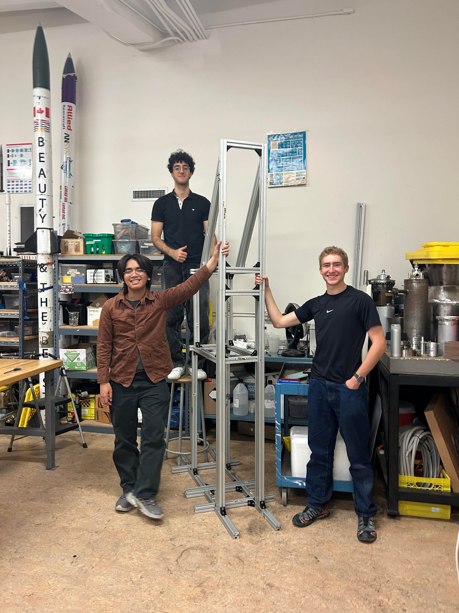
Recently I joined the UBC Rocket student design team. We’ve previously won first place at Spaceport America, static fired multiple liquid rocket engines, and have alumni working at all the space companies you know.
Recently, we’ve started a new program to make a Half Cat Mojave Sphinx liquid rocket and static fire it in the coming months. As part of this program, we assembled a test stand (shown above) in about a week from Aluminum Extrusion we had in the shop. By vibes and pushing hard on the test stand it looked like this test stand would work well, but I had some free time on a flight to the sphere recently so I tested Claude’s ability to do Solid Mechanics.
Overview
High level model overview:
- The output of this model is the factor of safety on every single test stand joint and member
- The test stand is a collection of 6 DOF joints
- Each joint provides a reaction force in x,y,z and moments in x,y,z by various mechanisms (friction & tensile / compression of the screw)
- A 2D & 3D model will be developed with a few simplifying assumptions to determine forces and moments on each joint
- All simplifying assumptions must be tested and confirmed to be valid
- Model outputs will be compared to allowable forces and moments on each joint
All code for this model is available on my GitHub (pending moving it to a UBC Rocket repo).
Triangle Bracket Free Body Diagram

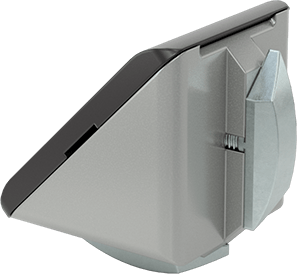
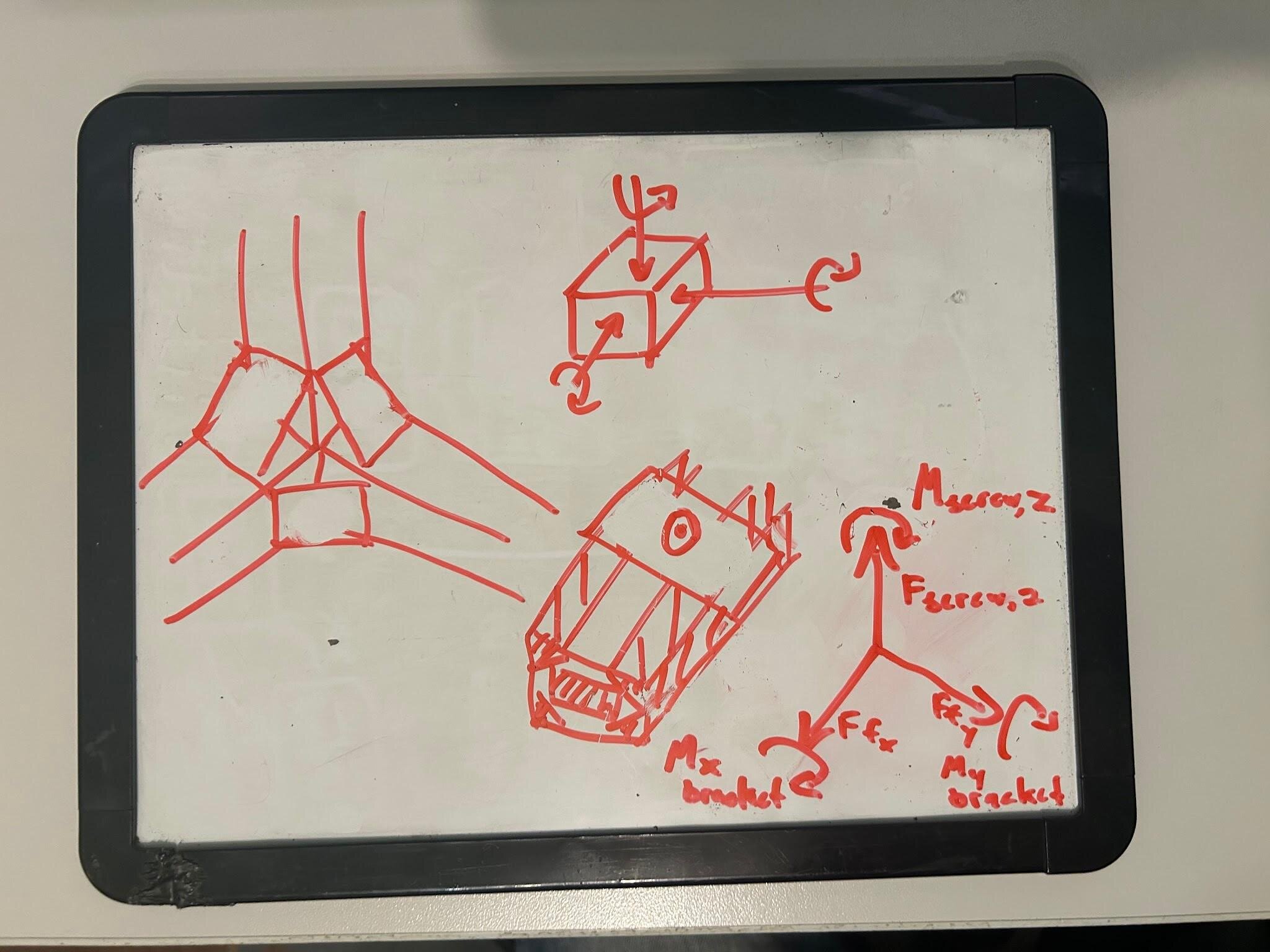
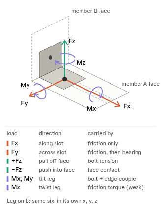
Each triangle bracket has two screw joints. Both of these joints can resist forces and moments in x,y,z.
Forces:
- X force is resisted by friction
- Y force is resisted by friction
- Z force
- Compression is resisted by the faces in contact
- Tension is resisted by the screw
- The full system is the screw, T-nut, and faces in contact with the aluminum extrusion
Moments:
- X moment is resisted by face contact
- Y moment is resisted by face contact
- Z moment is resisted by friction
- In an alternative case, there is a bracket that reacts against the channel with an anti-rotation key
Because each triangle bracket has two joints, there are pairs of forces for each bracket.
For example, referencing Claude’s diagram above, positive Z force on member A is resisted by the screw in tension whereas the same force on the member B joint is resisted by friction against the bracket and the aluminum extrusion.
Maximum Allowable Forces & Moments
Assumptions:
- Bolt preload: 5 kN
- Static coefficient of friction = 0.2
- Bracket side-length = 0.0254 m (1 inch)
Forces:
- X (friction): 5 kN × 0.2 = 1 kN
- Y (friction): 5 kN × 0.2 = 1 kN
- Z (compression) = 100 kN
- Yield strength of aluminum is ~200 MPa, assumed force is over 1 in²
- This is not limiting.
- Z (tensile) = 5 kN (equal to bolt preload)
Moments:
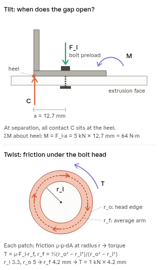
- X (face contact) = 63 Nm
- 5 kN screw force × (25.4/2 mm) = 63.5 Nm
- Y (face contact) = 63 Nm
- By symmetry to X moment
- Z (friction) = 4.2 Nm (very weak)
- Effective friction radius = 4.2 mm
- Screw shaft radius = 3.3 mm
- Screw head radius = 5 mm
-
- = static coefficient of friction
- Effective friction radius = 4.2 mm
- Z (channel) = 36 Nm
- Channel length = 20 mm
- Contact area = 3x3 mm = 9 mm² (assumption)
- Aluminum yield strength ~= 200 MPa
- Max force before yield: 0.000009 m² × 200e6 N/m² = 1800 N
- 1800 N × 0.02 m = 36 Nm
Joining Plate Free Body Diagram
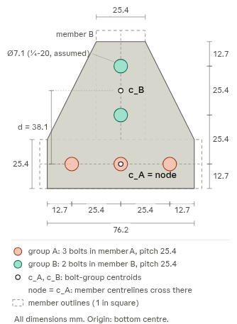
The joining plates are a special case of the brackets where the same joint is used 5 times on the same plane, instead of twice on planes that are 90 degrees from each other. Note that the joints are split into two groups, A and B, depending on the member they attach to.
Because there are multiple joints per member, we need to solve the indeterminate forces to find how much of each force is distributed along each joint.
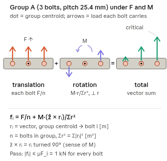
Each bolt group is in line, so the split has a closed form. Force is shared equally. Moment is shared in proportion to each bolt’s signed distance from the group centroid (illustrated in the first diagram of this section), acting perpendicular to the line. The centre bolt of a 3-bolt group carries no moment.
Maximum Allowable Forces & Moments
Assumptions:
- Bolt preload: 5 kN
- Static coefficient of friction = 0.2
Group A (3 bolts in member A, at r = −25.4, 0, +25.4 mm from the group centroid):
- Forces:
- X (friction, along slot): 3 × 5 kN × 0.2 = 3 kN
- Friction only; nothing positively stops the bolts sliding along the slot
- Y (friction, across slot): 3 × 5 kN × 0.2 = 3 kN
- T-nuts bear on the slot walls after slip (reserve)
- Z (compression): not limiting
- Plate bears directly on the extrusion face
- Z (tensile) = 3 × 5 kN = 15 kN (bolt preload × number of bolts)
- X (friction, along slot): 3 × 5 kN × 0.2 = 3 kN
- Moments:
- Z (friction, in-plane twist) = 50.8 Nm
- = 0.2 × 5 kN × (2 × 25.4²) / 25.4 mm = 50.8 Nm
- Centre bolt carries no moment (r = 0)
- X (about the bolt line) = 88.7 Nm (plate bending governs)
- Prying about plate edge: 3 × 5 kN × 12.7 mm = 190.5 Nm
- Plate bending through bolt row: = 241 MPa × 54.8 mm × (6.35 mm)² / 6 = 88.7 Nm
- = 76.2 mm − 3 holes × 7.14 mm = 54.8 mm
- Y (tilting along the line) = 88.7 Nm (plate bending governs)
- Bolt couple: = 5 kN × 50.8 mm = 254 Nm
- Plate bending through vertical centreline: = 88.7 Nm
- = 76.2 mm − 3 holes × 7.14 mm = 54.8 mm
- Z (friction, in-plane twist) = 50.8 Nm
Group B (2 bolts in member B, at r = ±12.7 mm from the group centroid):
- Forces:
- X (friction, along slot): 2 × 5 kN × 0.2 = 2 kN
- Y (friction, across slot): 2 × 5 kN × 0.2 = 2 kN
- Z (compression): not limiting
- Z (tensile) = 2 × 5 kN = 10 kN
- Moments:
- Z (friction, in-plane twist) = 25.4 Nm (weakest plate DOF)
- = 0.2 × 5 kN × (2 × 12.7²) / 12.7 mm = 25.4 Nm
- X (about the bolt line) = 59.1 Nm (plate bending governs)
- Prying about plate edge: 2 × 5 kN × 12.7 mm = 127 Nm
- Plate bending along the B line: = 241 MPa × 36.5 mm × (6.35 mm)² / 6 = 59.1 Nm
- = 50.8 mm − 2 holes × 7.14 mm = 36.5 mm
- Y (tilting along the line) = 91.3 Nm (plate bending governs)
- Bolt couple: = 5 kN × 25.4 mm = 127 Nm
- Plate bending through lower B hole: = 91.3 Nm
- = 63.5 mm − 7.14 mm = 56.4 mm
- Z (friction, in-plane twist) = 25.4 Nm (weakest plate DOF)
Claude did the math above.
Model Parameters
- Target safety factor: 4+
- Due to engine startup causing a large jerk, we need a dynamic safety factor of at least 2, and we add 2x on top of that
- 6061 T6 8020 Aluminum Extrusion
Model variations:
- Pin joints
- A pinned joint passes forces but no moments. So, the angle between the members is free.
- Resistance to rotation is modelled using a torsional spring at every pin joint with spring constant (weak spring relative to the members’ stiffness)
- This case is the worst-case for the members, in which all moments are transferred as forces over the members.
- Rigid joints
- Rigid joints pass both forces and moments
- This case models the worst-case for the joints, in which moments are carried entirely by the joints.
- Non-Continuous Members
- Not all members are continuous
- These discontinuous joints are modelled through two methods
- Assume compression through the member end faces
- Assume force is transferred through brackets, none on the faces (conservative case)
By using the worst-case values from the pin joints, rigid joints, and non-continuous member cases we can find the most conservative estimate of safety factor.
Member failure will be modeled using:
- Yield strength
- Axial yield strength equals the yield strength of Aluminum
- Bending yield strength uses the distance from the neutral axis of each beam (member in bending)
- Combined axial + bending stress:
- N = axial force [N], A = cross-sectional area [m²]
- , = bending moments about the member’s two cross-section axes [N·m]
- = section modulus [m³], where c = 12.7 mm is the distance from the neutral axis to the outer face
- Failure occurs when
- Taking absolute values assumes the peak stress from each term lands at the same corner, which is conservative
- Buckling (members in compression)
- From MECH360:
- is the critical force [N] at which a member buckles
- Failure occurs when:
- if
- if
- K = 1.0 (conservative case for a beam pinned at both ends)
- From MECH360:
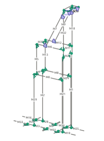
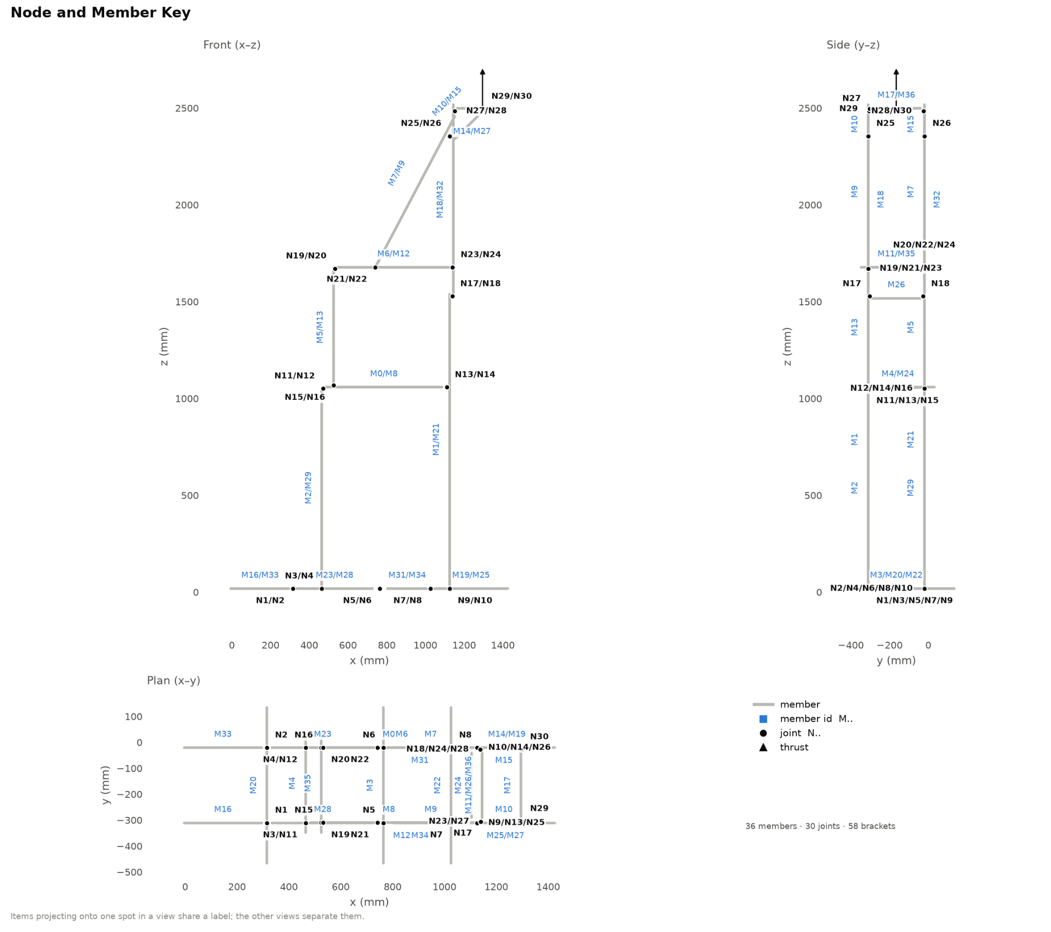
This diagram shows an export of the CAD along with every angle bracket and plate bracket. This model is available here.
Model Validation
In the spirit of the great Graham Hendra, I backtested this model using his Burrard St. Bridge worked example. He models the bridge as a truss with pin joints and examines the members in buckling.
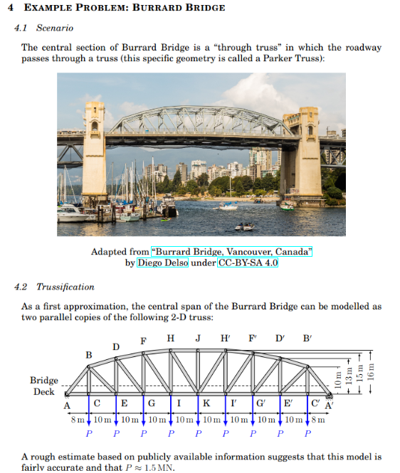
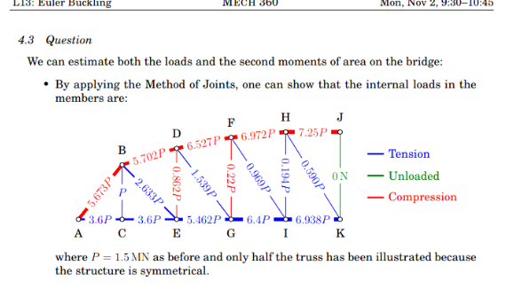
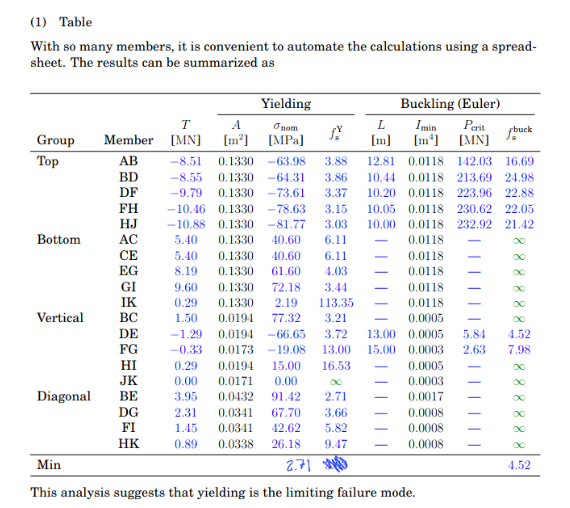
Burrard Street Bridge Validation Results
All values in my model are equal to the provided 3 sig fig values in Graham Hendra’s model. The model passed this back test / validation.
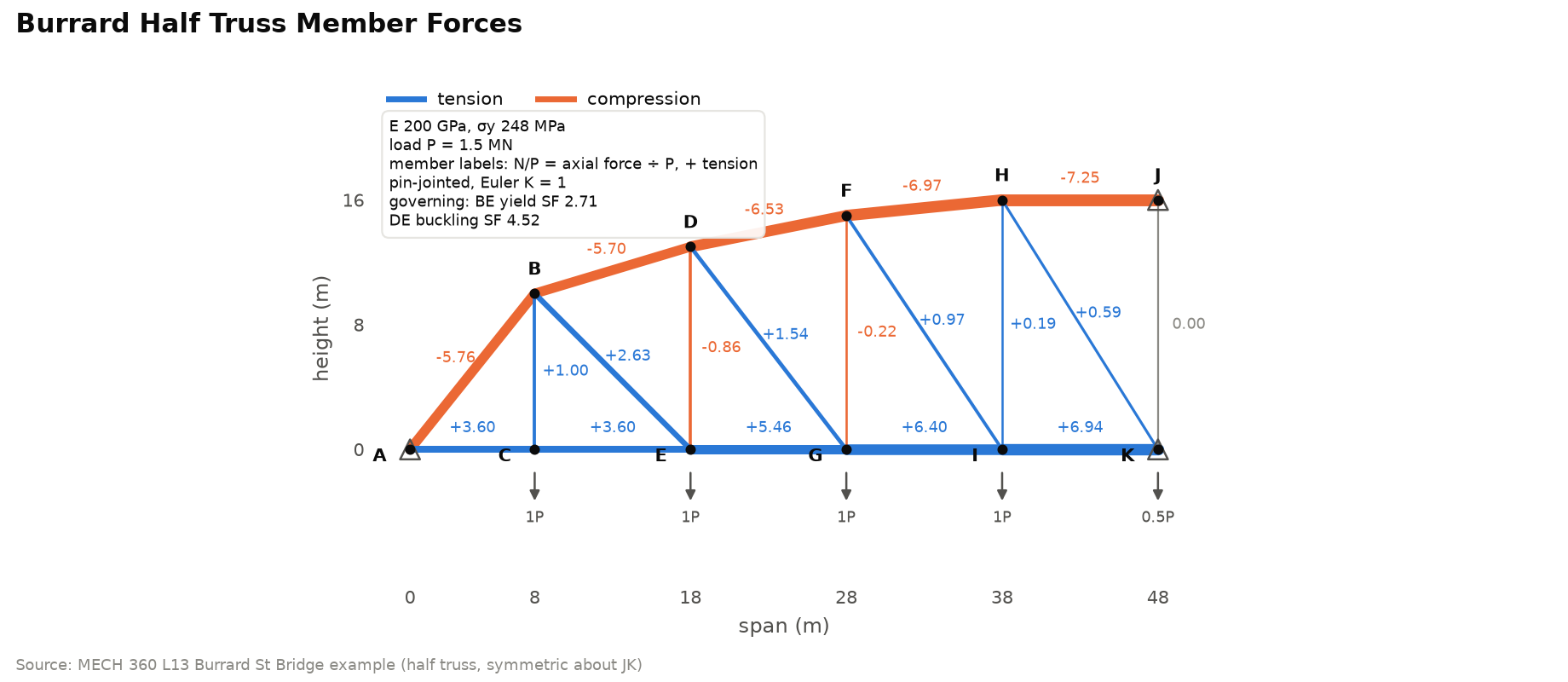
Member Forces
| member | N (MN) | N/P | notes N/P | match |
|---|---|---|---|---|
| HJ | -10.875 | -7.250 | -7.250 | yes |
| FH | -10.458 | -6.972 | -6.972 | yes |
| DF | -9.790 | -6.527 | -6.527 | yes |
| AB | -8.644 | -5.763 | -5.763 | yes |
| BD | -8.553 | -5.702 | -5.702 | yes |
| DE | -1.292 | -0.862 | -0.862 | yes |
| FG | -0.330 | -0.220 | -0.220 | yes |
| JK | +0.000 | +0.000 | +0.000 | yes |
| HI | +0.291 | +0.194 | +0.194 | yes |
| HK | +0.884 | +0.590 | +0.590 | yes |
| FI | +1.453 | +0.969 | +0.969 | yes |
| BC | +1.500 | +1.000 | +1.000 | yes |
| DG | +2.309 | +1.539 | +1.539 | yes |
| BE | +3.949 | +2.633 | +2.633 | yes |
| AC | +5.400 | +3.600 | +3.600 | yes |
| CE | +5.400 | +3.600 | +3.600 | yes |
| EG | +8.192 | +5.462 | +5.462 | yes |
| GI | +9.600 | +6.400 | +6.400 | yes |
| IK | +10.406 | +6.938 | +6.938 | yes |
Member Buckling Safety Factors
| member | SF yield | notes | P_crit MN | notes | SF buckling | notes |
|---|---|---|---|---|---|---|
| BE | 2.71 | 2.71 | ||||
| HJ | 3.03 | 3.03 | 232.92 | 232.92 | 21.42 | 21.42 |
| FH | 3.15 | 3.15 | 230.62 | 230.62 | 22.05 | 22.05 |
| IK | 3.17 | |||||
| BC | 3.21 | 3.21 | ||||
| DF | 3.37 | 3.37 | 223.96 | 223.96 | 22.88 | 22.88 |
| GI | 3.44 | 3.44 | ||||
| DG | 3.66 | 3.66 | ||||
| DE | 3.72 | 3.72 | 5.84 | 5.84 | 4.52 | 4.52 |
| AB | 3.82 | 3.88 | 142.03 | 142.03 | 16.43 | 16.69 |
| BD | 3.86 | 3.86 | 213.69 | 213.69 | 24.98 | 24.98 |
| EG | 4.03 | 4.03 | ||||
| FI | 5.82 | 5.82 | ||||
| AC | 6.11 | 6.11 | ||||
| CE | 6.11 | 6.11 | ||||
| HK | 9.48 | 9.47 | ||||
| FG | 13.00 | 13.00 | 2.63 | 2.63 | 7.98 | 7.98 |
| HI | 16.55 | 16.53 | ||||
| JK | — |
Model Diagrams
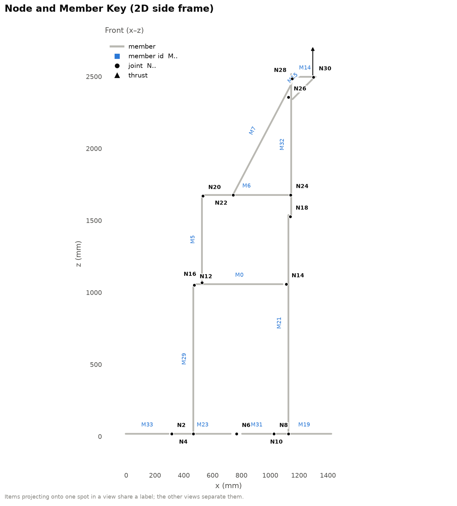
These diagrams of the 2D and 3D models define all nodes and members.
2D Model
3D Model
2D Model
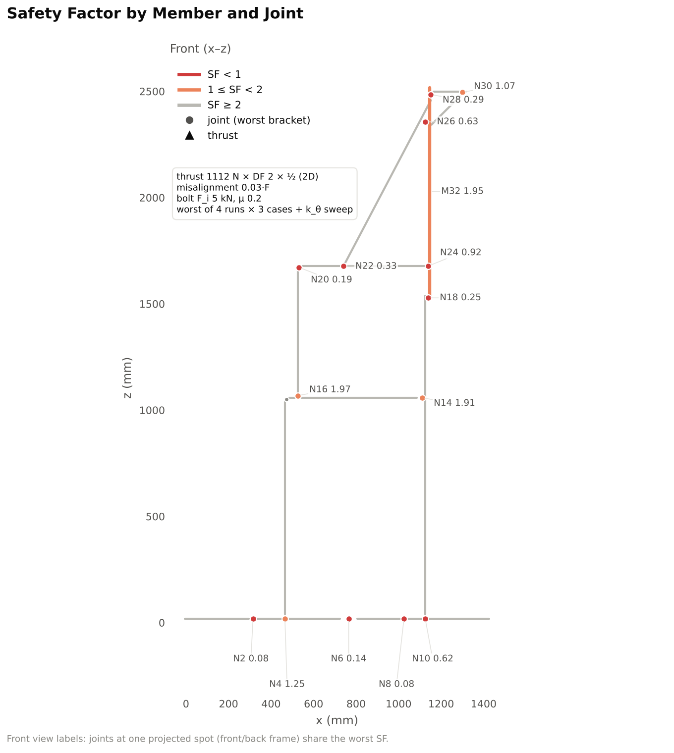
Finally, we can solve the system that corresponds with our test stand. We will apply a 250 lbf (1112 N) upward force on the member that corresponds with the rocket, then calculate the force and moment on each joint, and finally determine each safety factor.
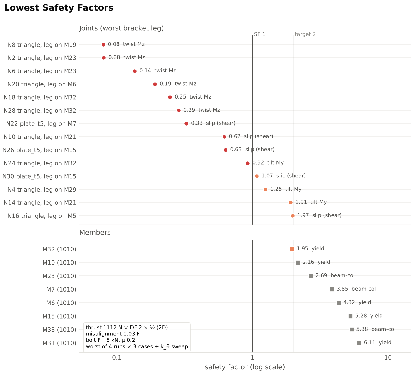
Below, we see that the lowest safety factor is 0.08, and the system fails. The limiting factor is the Z-axis moment that must be resisted by friction on each joint.
A safety factor of 0.08 suggests that a force of just 20 lbf would cause the stand to fail (safety factor = 1). We’ve applied more force than this ourselves, so before we continue we must define what failure is occurring and discuss if the model is valid.
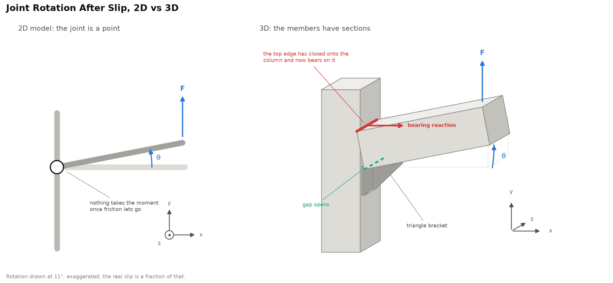
Joint failure in Z-axis moment means that the joint starts rotating as shown in the left diagram above. This failure means that friction force no longer resists the moment and the members move until they settle into a new equilibrium.
In 2D, this means that we get rotation of the joint. Given the Free Body Diagrams we constructed of the brackets, this 2D behaviour clearly doesn’t fully capture what we would see in 3D. So, we must model our test stand in 3 dimensions.
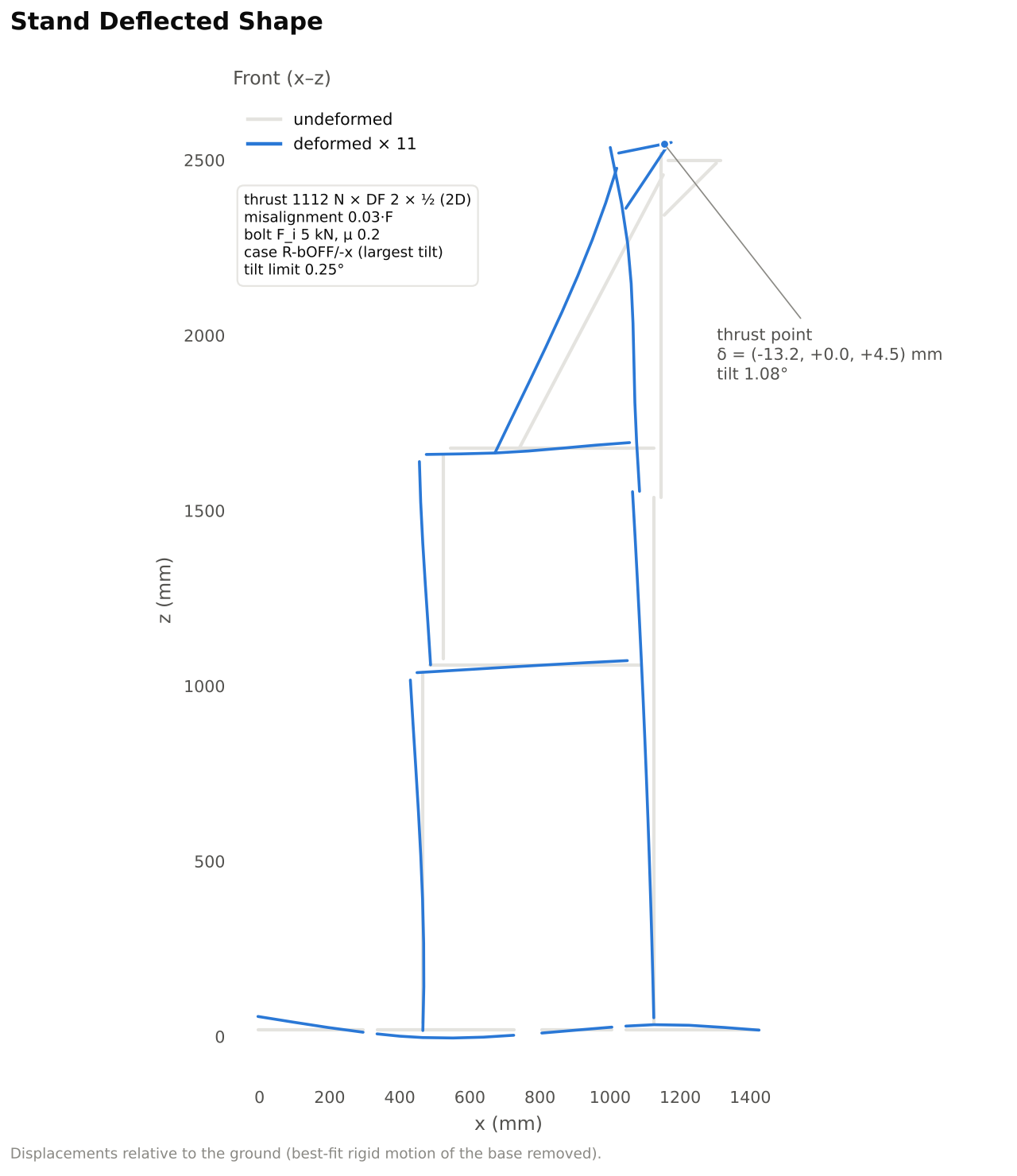
This extreme deformation is also something that we should look into. In the next section we’ll see that it is not present when we model this problem in 3D.
This 2D modelling section has been a lesson in being careful what simplifying assumptions you make.
3D Model
Our 3D model still has a minimum safety factor of 0.08, but on an entirely different set of joints.
In the charts below, notice that joints on the ground (N5, N7, N6, etc.) have the lowest safety factors. This is because the bottom of the test stand does not consist of continuous members, instead it is made of ~10 sections of aluminum extrusion because that is what we had on hand.
Every joint between these disparate sections of aluminum extrusion carries a high moment (because they are offset ~1 inch from each member, so they’re not directly in the force path). This leads to the high Z-axis moments that cause these low safety factors.
So far it’s not looking good for our test stand design at all!
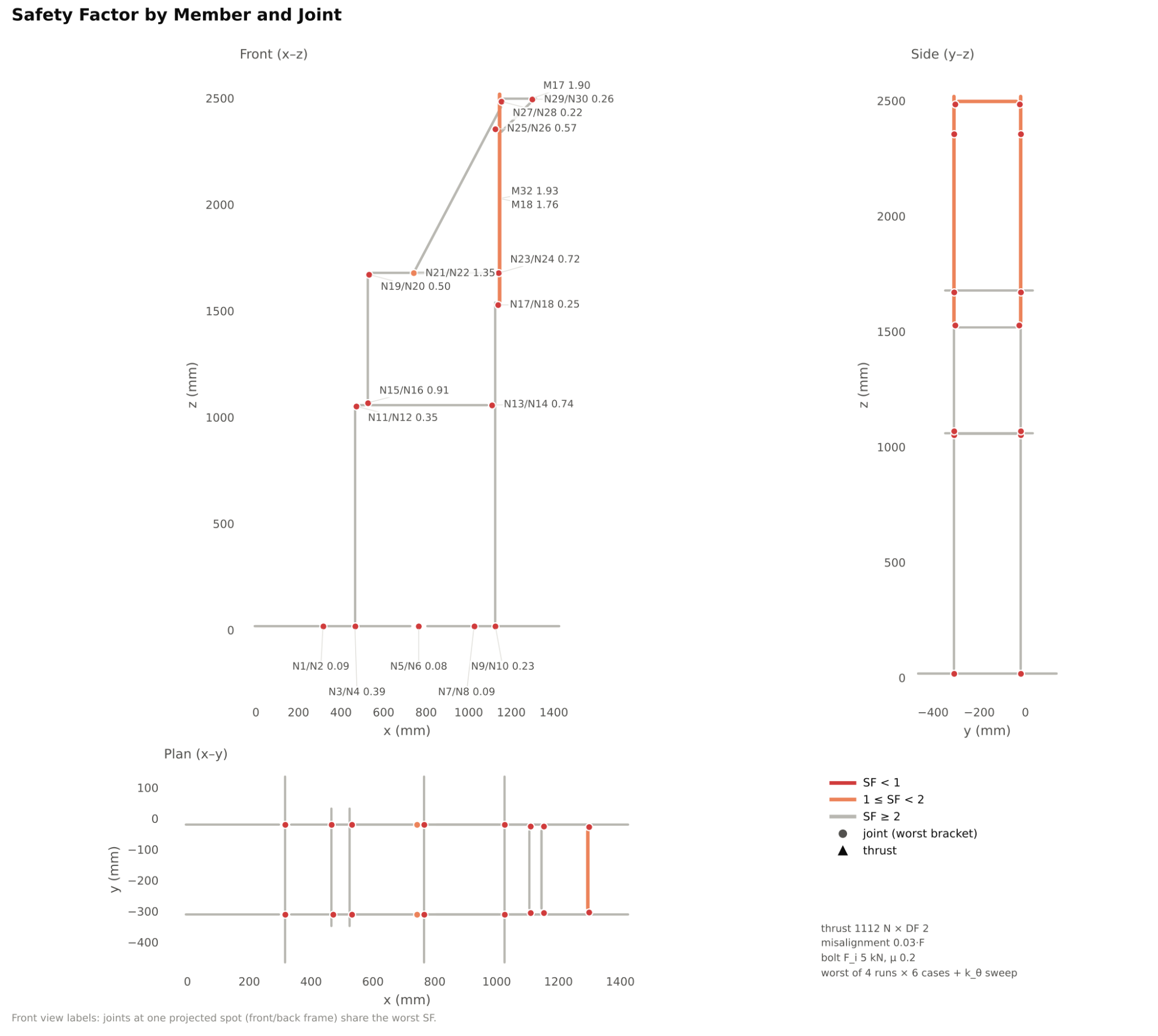
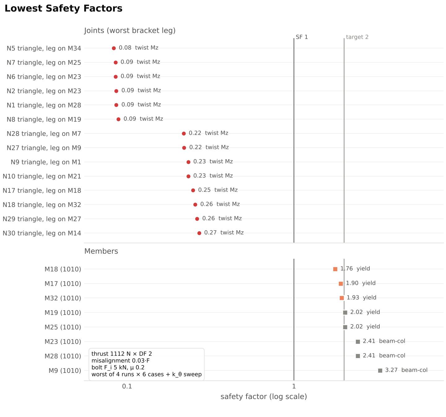
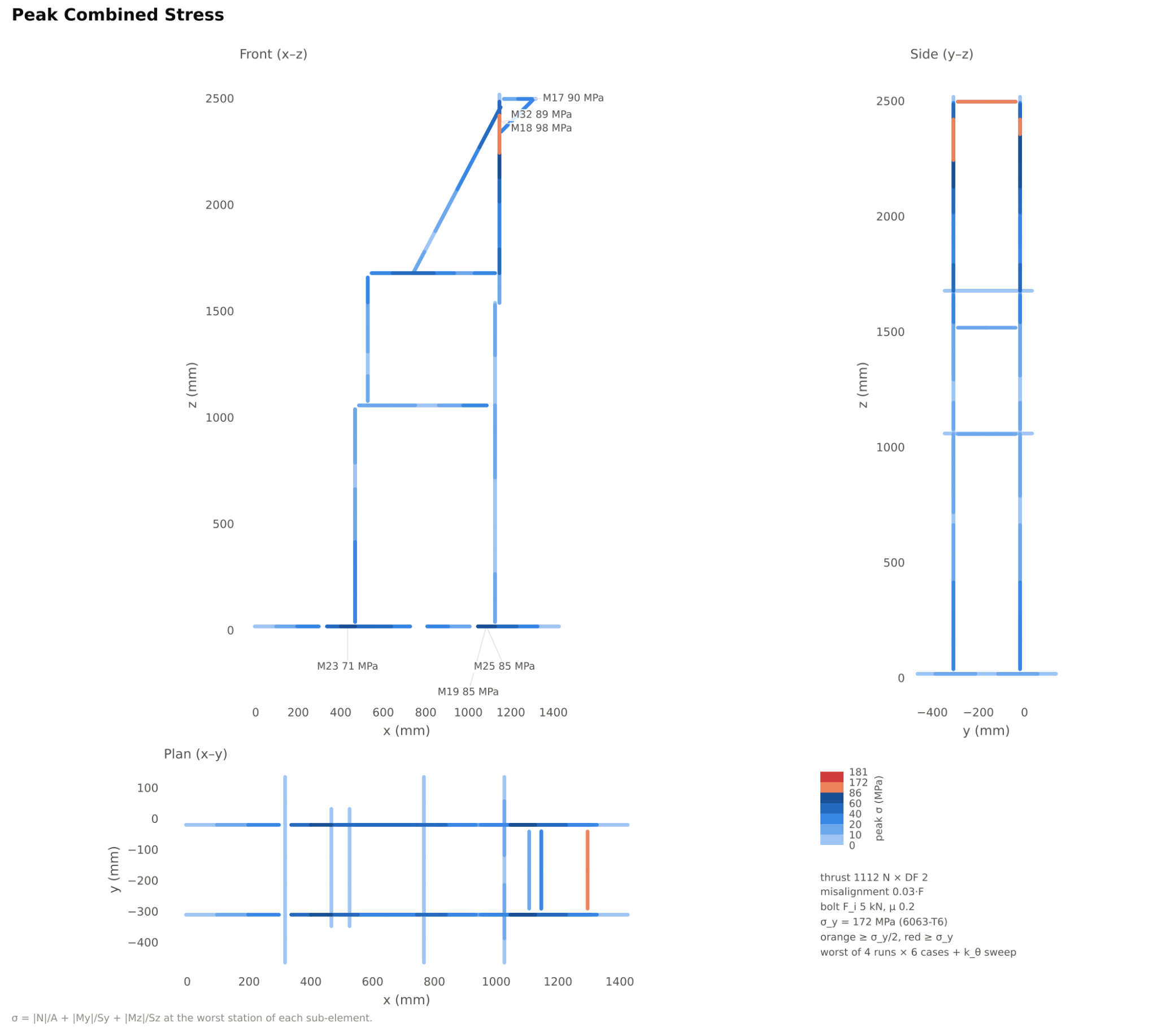
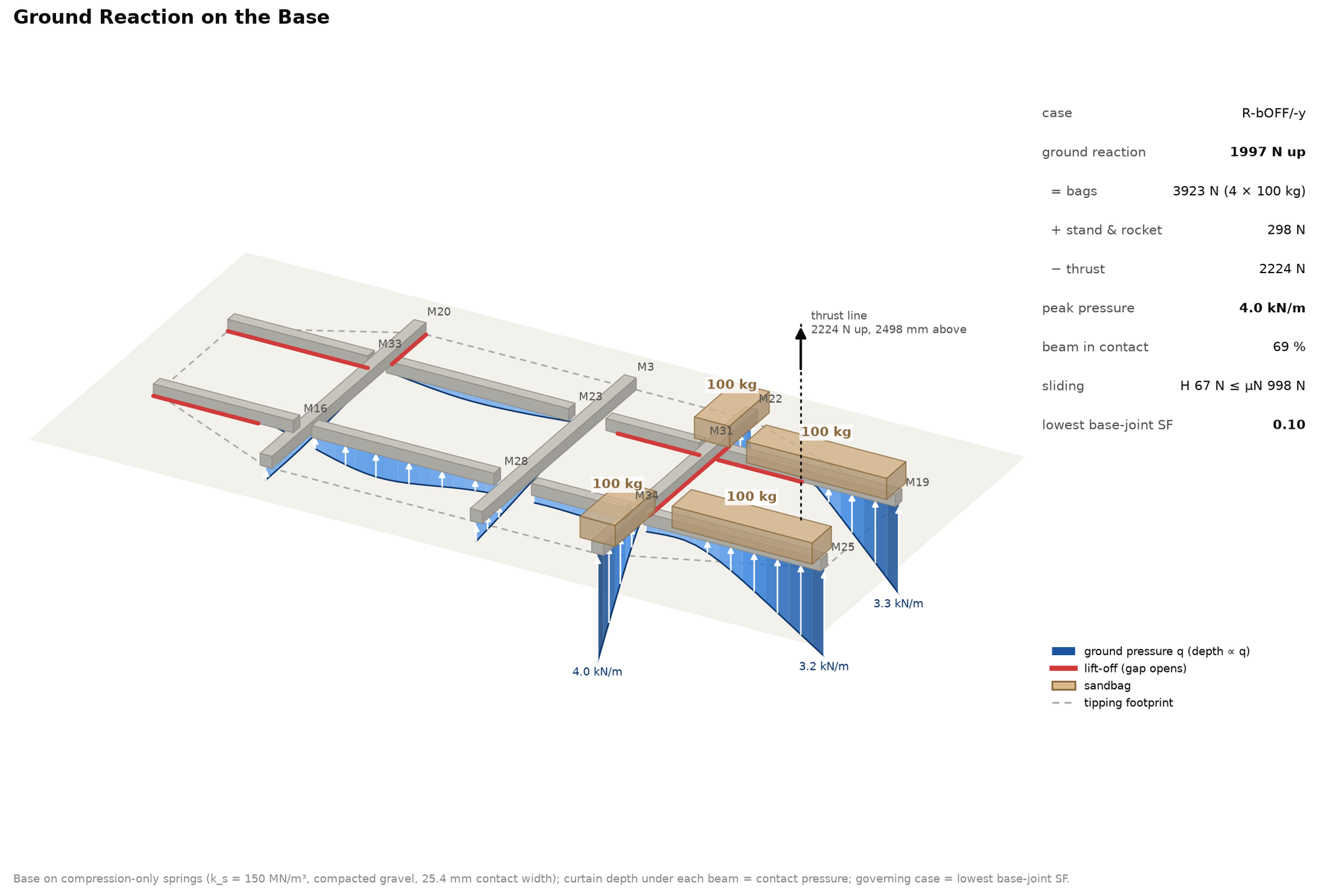
To get the distribution of ground reaction forces this model used an array of high-stiffness springs on the surface to find where the most tension and compression lies. More implementation details are available in the GitHub repo.
Anti-Rotation Key 2D & 3D Simulations
In the previous simulations we found that the limiting safety factor was Z-axis moment on each joint. A potential solution to this problem is using triangle brackets that have anti-rotation keys. These slot into the 8020 channel and allow us to resist moment with normal force on the inside of the channel instead of purely friction.
For reference, we previously had a maximum moment of 4.2 Nm and now we’re up to 36 Nm.
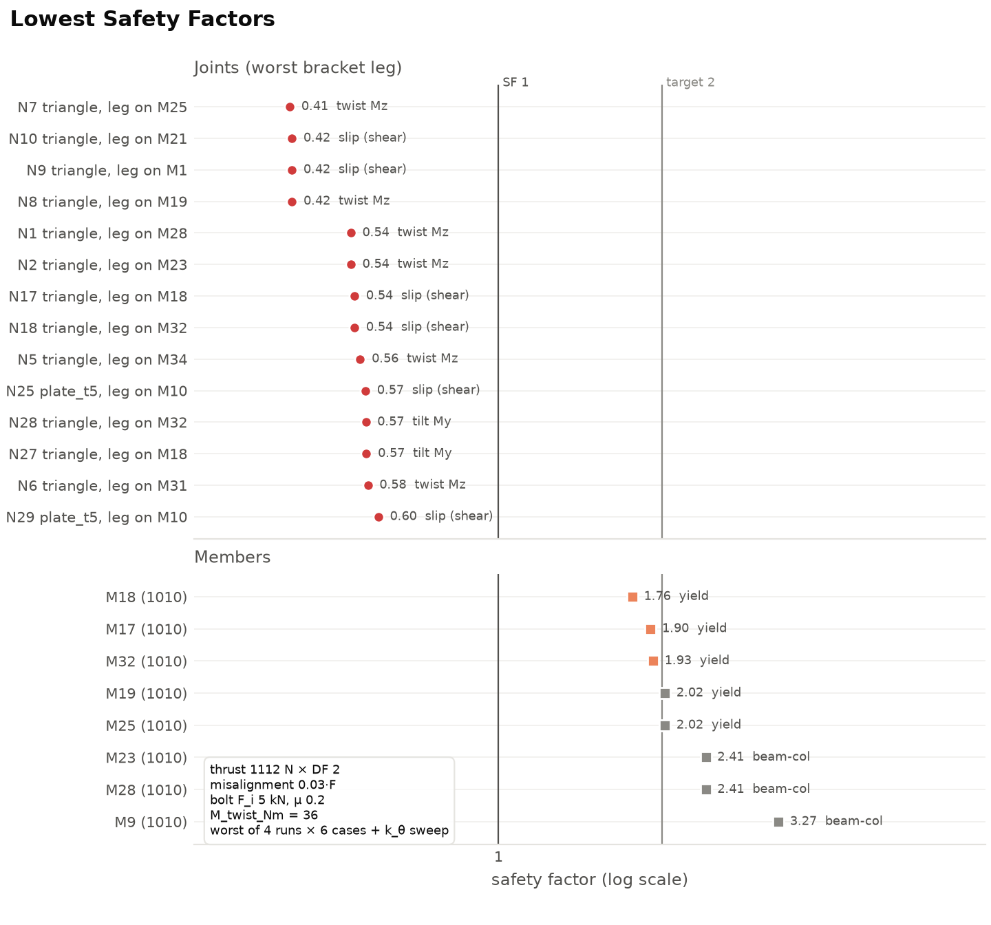
In the chart above we can see that Z-axis moment is still our limiting factor. However, other failure modes like slip are relatively more important as they are now on the same order of magnitude of safety factor.
Conclusion
The current design of our 8020 aluminum extrusion test stand will fail during a static fire and cannot be used.
This model doesn’t perfectly reflect reality, and in some ways it is conservative and in others it underestimates. For example, in some cases the Z-axis moment would be handled by members coming into contact with each other and transferring the moment through normal forces. An example of underestimation is that the model didn’t include any off-axis thrust forces, it assumed the thrust force is purely vertical.
Potential avenues for redesign of the test stand include:
- Using longer continuous members and fewer joints.
- Applying angle brackets in a manner that they don’t have a high Z-axis moment on them.
- Using more plate brackets instead of angle brackets.
- Replacing our aluminum extrusion design with a more traditional Half-Cat like test stand which consists mainly of a vertical metal pole secured to the surface.