I Made A Reflow Oven
Convection Toaster Ovens Just Happen To Be Perfect For Reflow Ovens
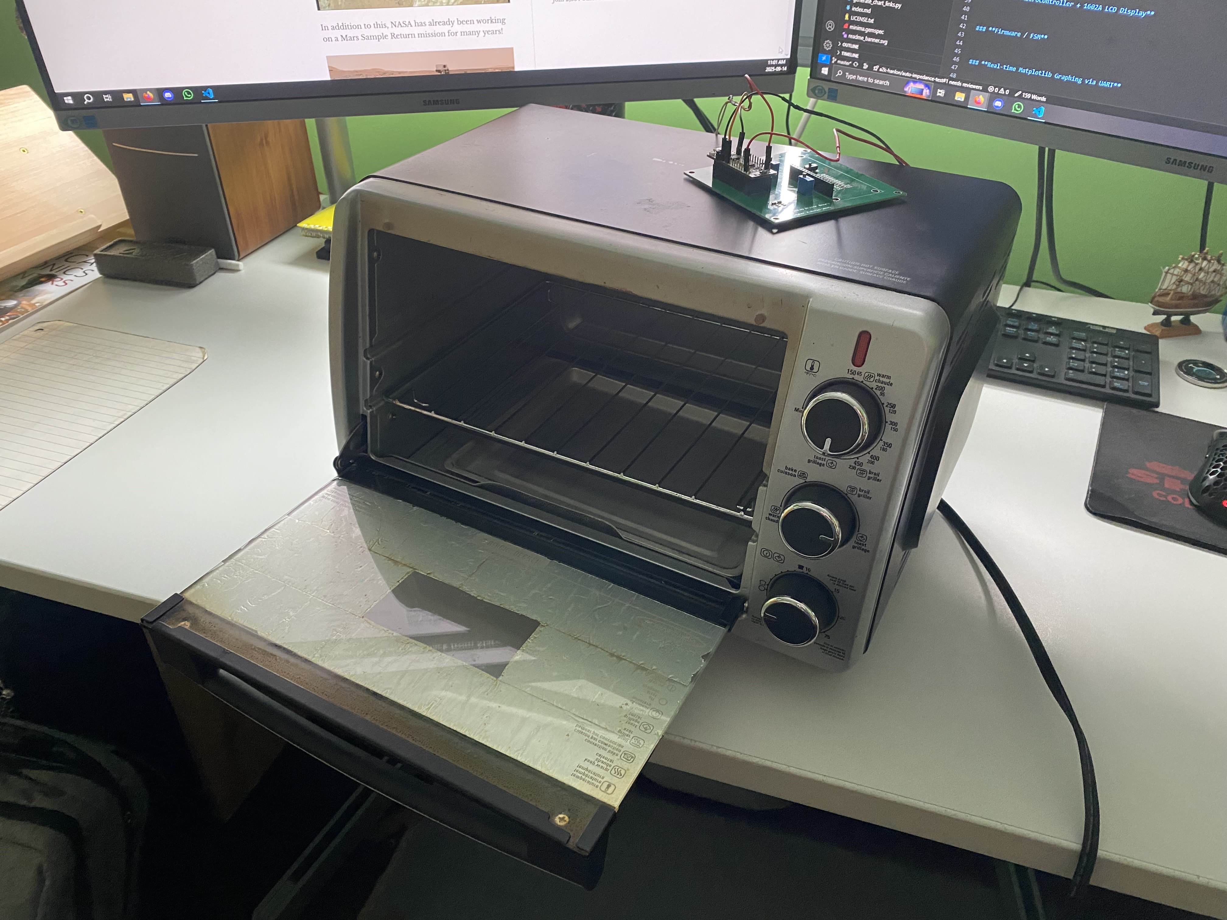
A couple of months ago I wanted to do thermal characterization testing on 3D printed filament to derive the yield strength vs temperature curve. On the critical path of this project is having an environment chamber that can be controlled to a precise temperature. This is essentially what a reflow oven does, and I’ve made several PCBs in the last few months, so I decided to make a reflow oven.
A convection toaster oven consists of a few heating elements, a fan to circulate the air, and various analog components for user input. A reflow oven consists of a few heating elements, a fan to circulate the air, and various digital components for user input. Lots of overlap!
Because most convection toaster ovens are completely analog systems, it is not too difficult to hack them so they can be controlled digitally with a Solid State Relay.
Part Selection
Solid State Relay
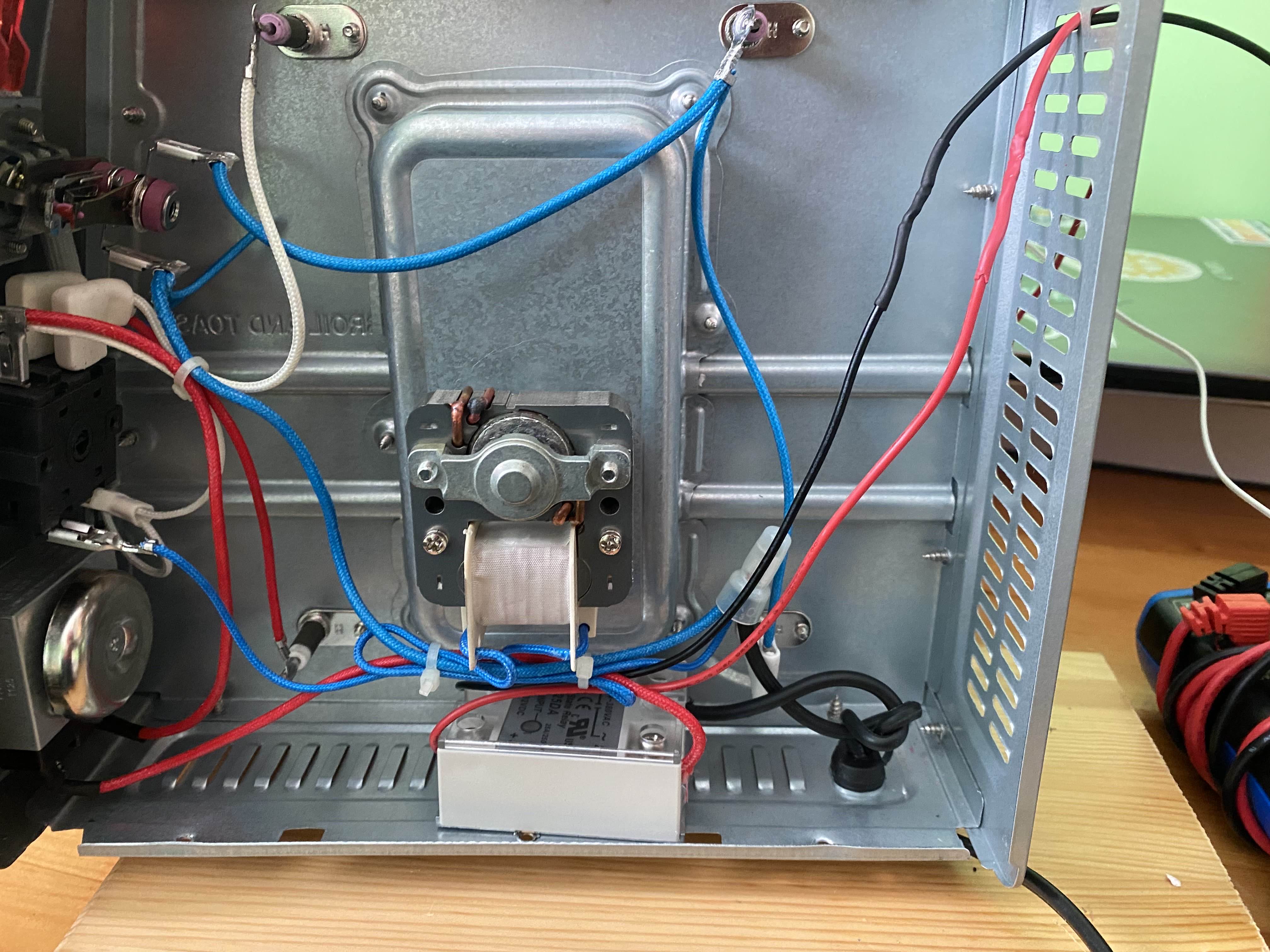
The SSR is in series with the 120 V AC input on the high-side.
Because precise control of temperature requires PWMing the heating elements, a Solid State Relay (SSR) is required. A mechanical relay / contactor would wear out rather quickly if switched many times per second. Switching time for a mechanical relay is also tens of milliseconds while SSRs switch in microseconds.
I chose the SSR-25DA and picked one up for $26 CAD from Lee’s Electronics here in Vancouver. It has a current limit of 25 A and a switching voltage range of 3 to 32 V DC. Because trigger current is only 7.5 mA, it can be driven directly from a 3.3V GPIO pin. STM32F031K6 GPIO pins can sink or source up to 15 mA in a subset of their voltage range (0.4 V to VDD - 0.4 V), see page 81.
Thermistor
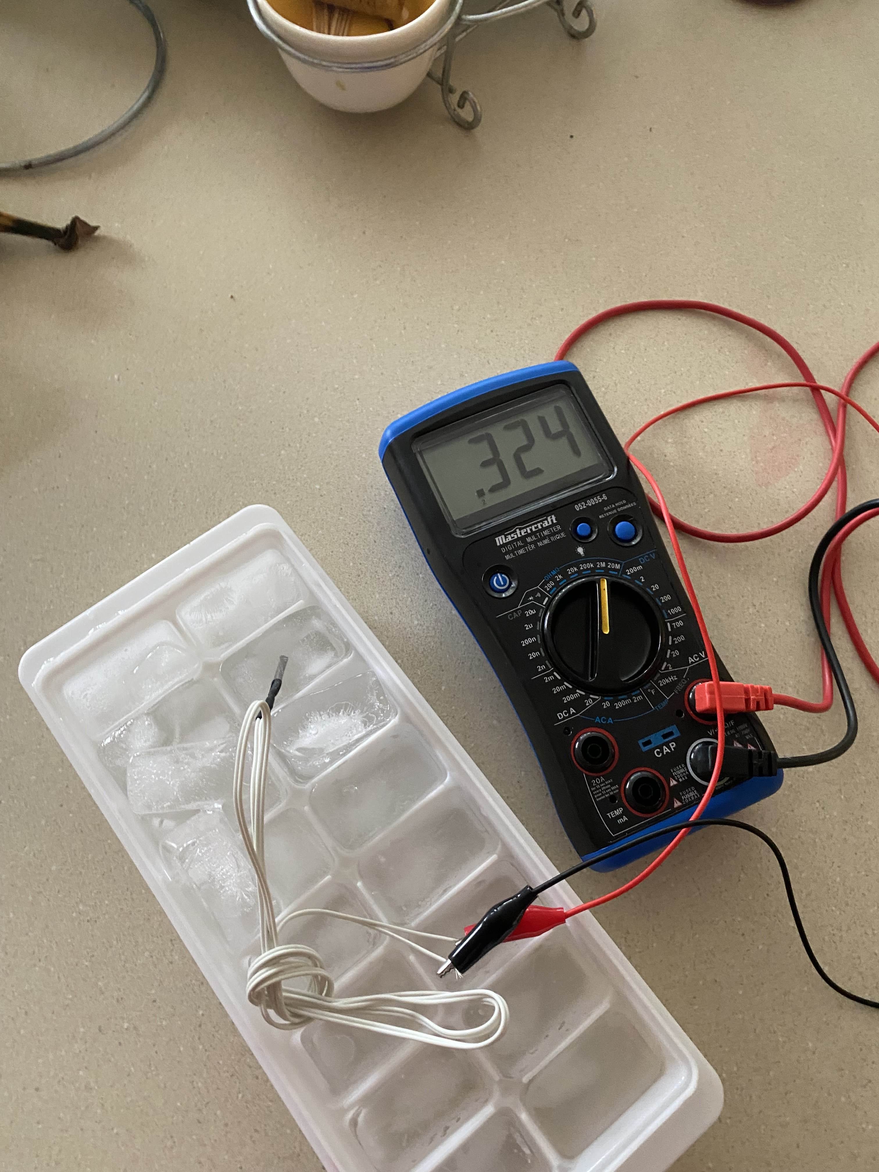
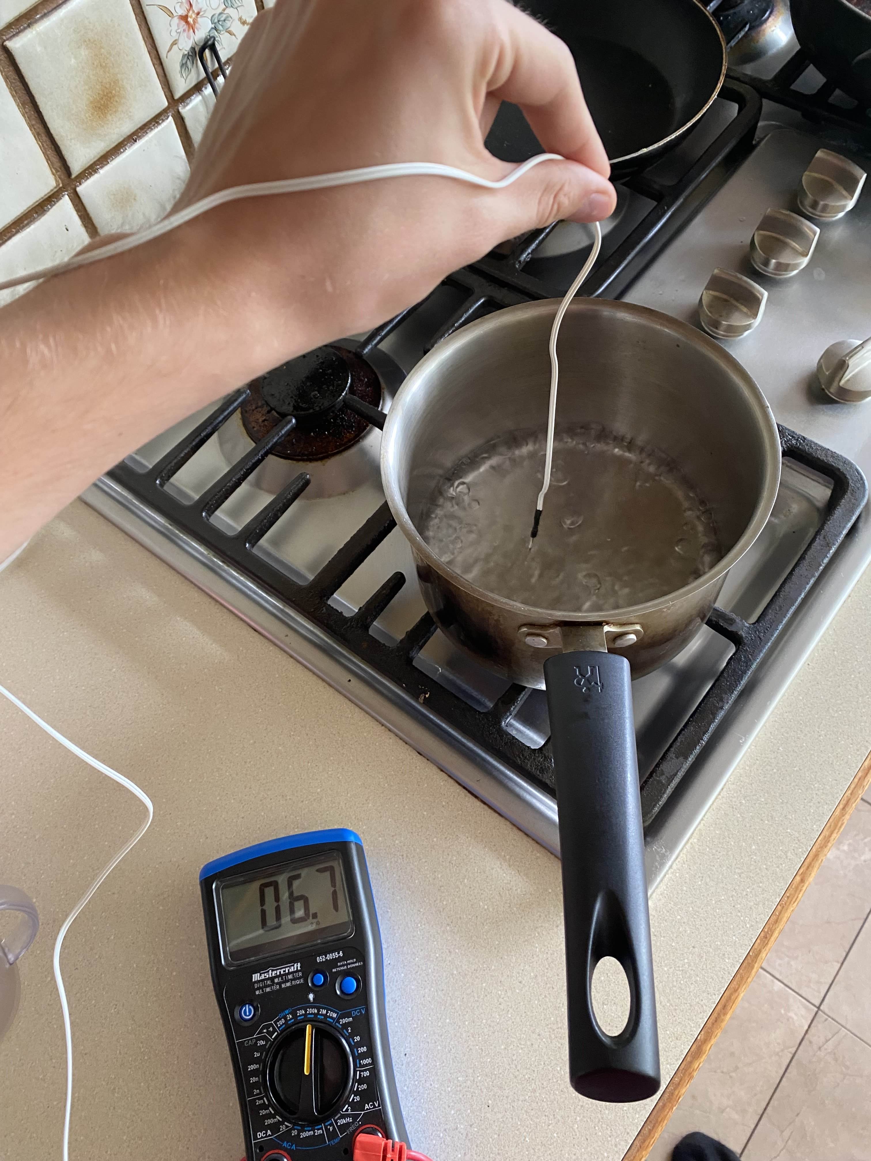
Hedging against potentially poor quality AliExpress parts by characterizing the thermistor. Results Here
I bought this NTC 100 K thermistor from AliExpress. NTC = negative temperature coefficient, meaning resistance decreases as temperature increases. 100 K means resistance is 100 kΩ at 25°C.
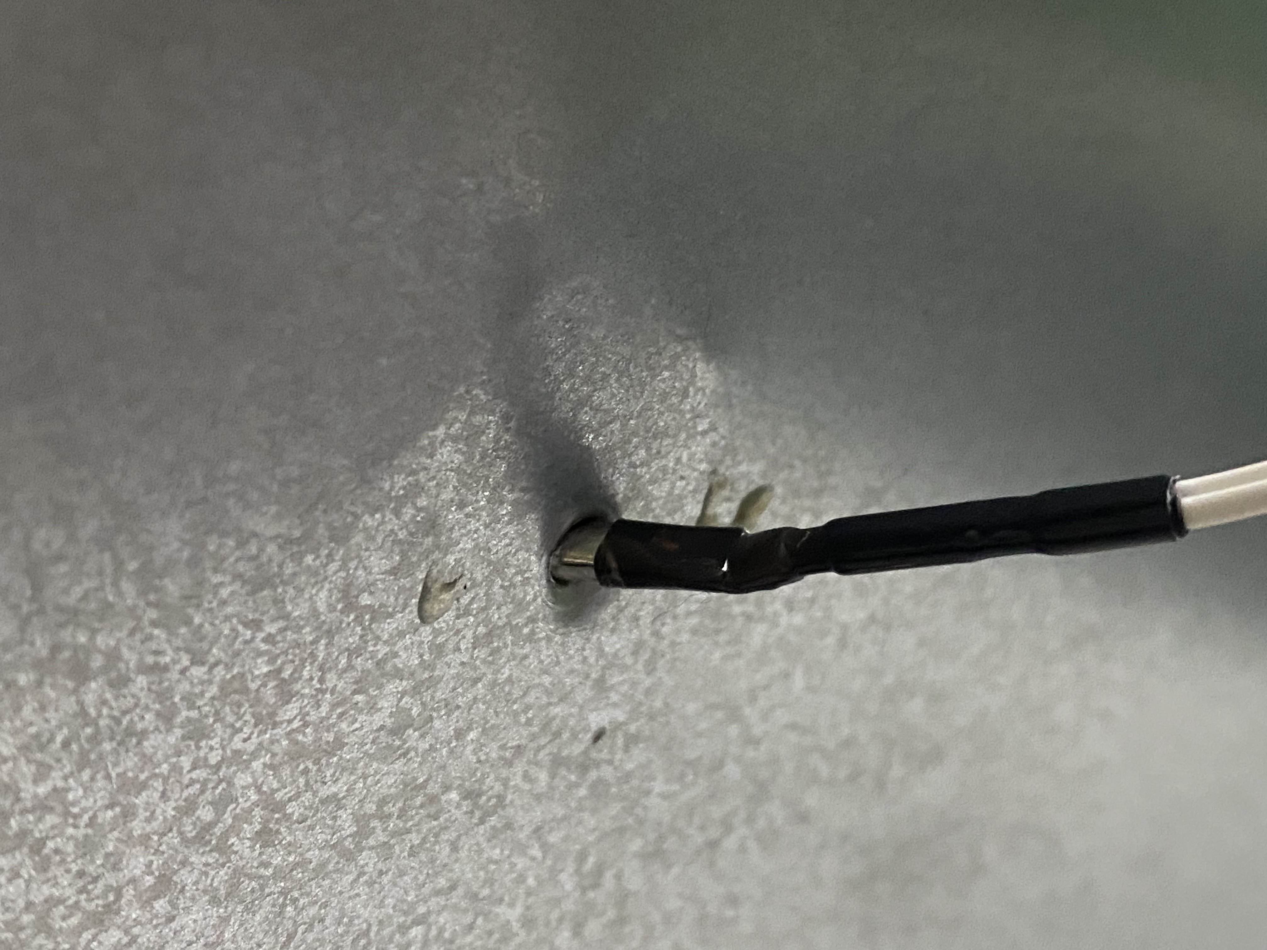
Electrical tape melts at ~80°C and I have no great thermal adhesive, so I cut a hole in the back of the oven and put the thermistor through it. I’ve unfortunately returned to being a busy engineering student so this solution to mounting the thermistor will have to suffice for now. I’ll just have to remember to check if it’s fallen out! Kapton tape seems like the right solution here, at some point in the future I’ll buy some.
To convert a resistance to a voltage I used a voltage divider with a 1 kΩ resistor.
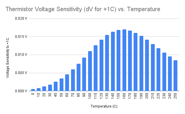
Slew rate of a voltage divider is greatest when both resistors are equal, and I wanted to optimize precision of temperature measurements in the relevant range for reflow soldering (~150°C to 250°C). At ~170°C the thermistor resistance is about 1 kΩ, so I chose a 1 kΩ resistor for the voltage divider.
Optimizing for a high slew rate is ideal because that means a single degree change in temperature will result in a greater change in voltage. With a constant ADC resolution, this means greater precision in temperature measurement.
For 3D-printer filament thermal characterization testing, I’ll likely want precise temperature measurements around 60-80°C, where the thermistor is around 15 kΩ, so I’ll swap out the 1 kΩ resistor. The 1 kΩ resistor is currently soldered in place to a wire, so I’ll likely make another thermistor harness to female jumper pin that can plug into my STM32.
STM32 Microcontroller + 1602A LCD Display
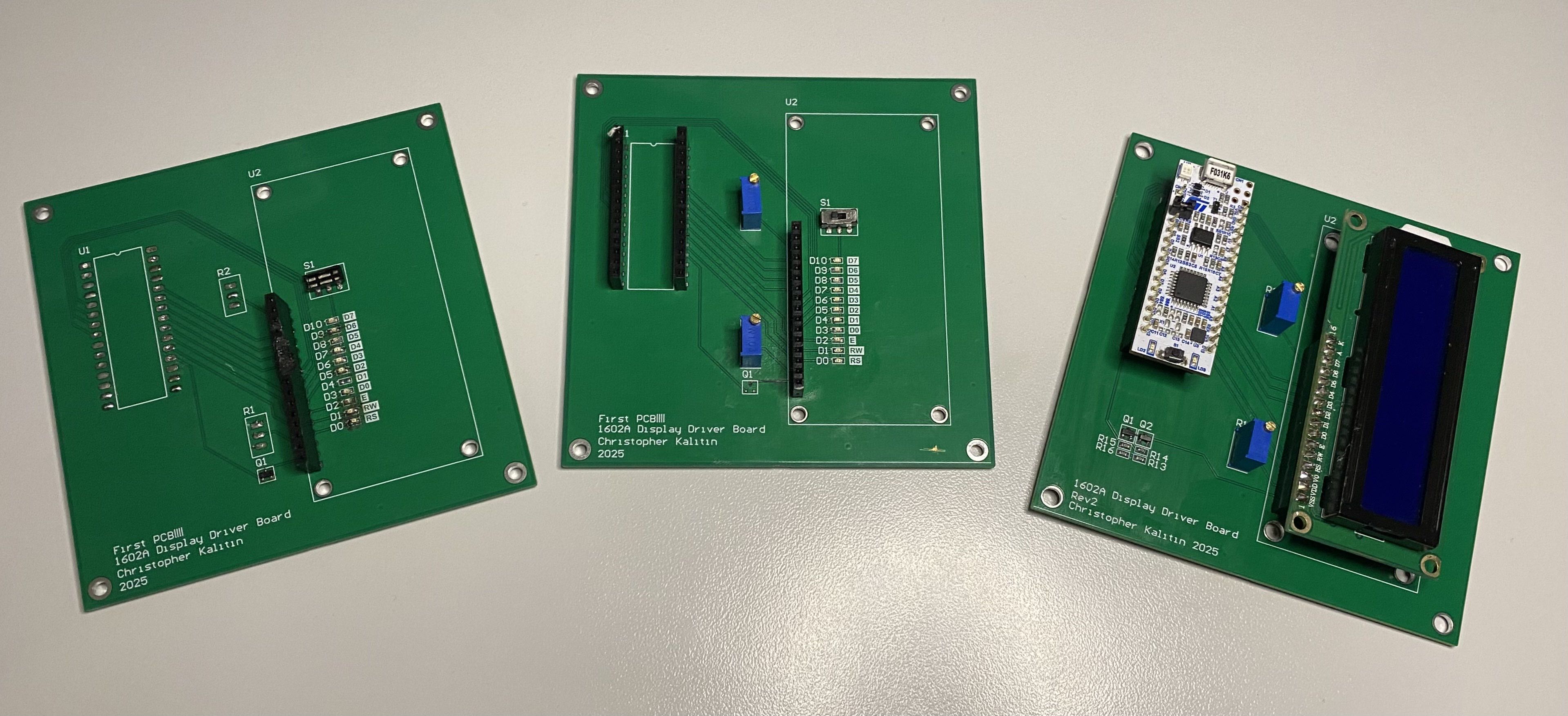
My first STM32 firmware project was writing a library to control a 1602A LCD display. A few months after writing that library, I made a PCB to interface between the 1602A display and the STM32F031K6T6 microcontroller.
This was my first PCB project so I just put female header arrays on the PCB so I could slot in the display and STM32 Nucleo. This meant all GPIOs were still accessible, unlike if I had soldered the STM32 directly to the PCB. So, I could use this PCB to display temperature and status information in real time while controlling the reflow oven.
Firmware / FSM
The firmware has 4 primary functions: reading temperature, displaying information on the LCD, controlling the SSR, and running an FSM to manage the reflow process.
Reading the thermistor voltage and converting it to a temperature reading is a slightly involved process because we start with a voltage, convert it to a resistance via the voltage divider equation, then convert resistance to temperature. Took longer than I’d like to have spent on this to derive the equation. See it in adc.c.
I copy and pasted my 1602A LCD library into this project, and it worked first try. The issue I ended up seeing with the LCD was that the 5V source from the USB was noisy and not constant. This meant the difference between VDD and V0 (the contrast voltage) was not constant, so the contrast of the display would vary. This meant one second the text could be perfectly visible, the next second all pixels are active, and the next second no pixels are active. I’ll have to solve this on a future revision by using a 5V regulator or using a DAC to set V0 (this makes it less user controllable, instead of turning a trimmer potentiometer we need to reflash).
Controlling the SSR is just a GPIO as I didn’t go for precise PWM control on my first iteration.
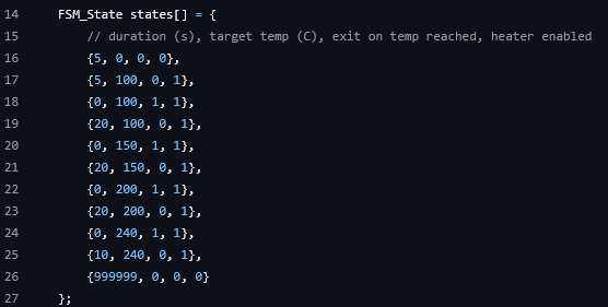
Each FSM state is made up of 2 variables and 2 flags: duration (s), target temperature (°C), exit on temperature reached (bool), heater enabled (bool). If exit on temperature reached is true, then the FSM goes into the next state when the target temperature is reached. Otherwise, a timer is used and is compared to the duration variable. Fairly simple.
The current FSM profile shown above was just an example one I made to test the system. It slowly goes up to 240°C over several minutes, then turns off and hopefully I remember to open the oven door to cool it down.
Fried ADC
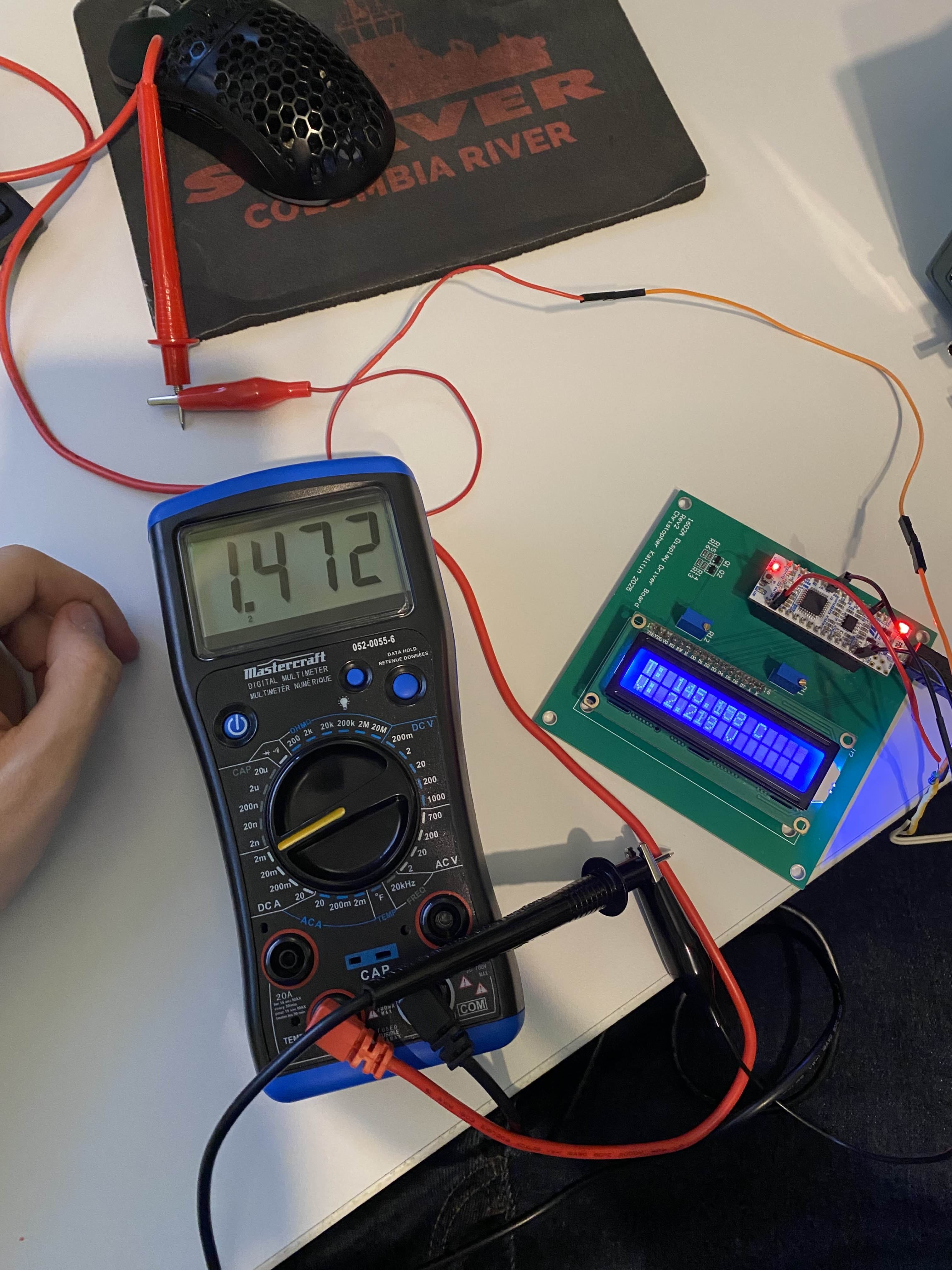
The multimeter is in series between the middle tap of the thermistor + 1k voltage divider and the ADC pin. We see 1.5 mA flowing into the ADC, clearly it’s fried.
While testing the firmware and reflow oven there was a point where the ADC was reading a constant voltage regardless of the temperature. After some testing, I found that the voltage in the middle of the divider changes depending on if the ADC pin is connected or not. Clearly current was flowing into the ADC pin instead of through the secondary resistor of the voltage divider. I used my multimeter and found 1.5 mA of current was flowing into the ADC. Clearly it was fried.
To solve this problem I used a different ADC pin and it worked fine. However, to get another ADC pin I had to repurpose a GPIO that was being used to control the LCD display. So, no more display, but we can read temperature!
Real-time Matplotlib Graphing via UART
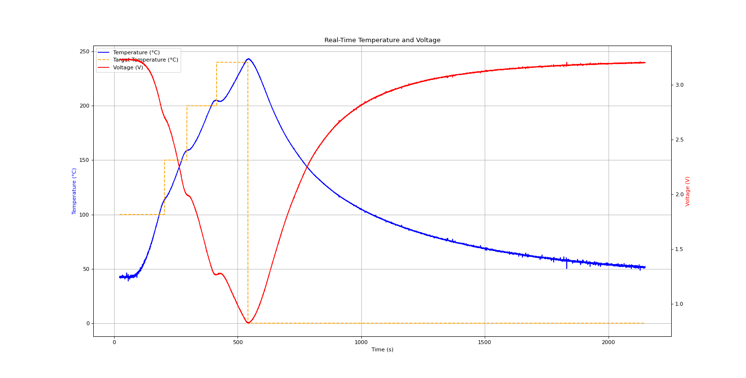 This shows a temperature profile test, then a cooldown phase with the door closed. More testing graphs are available in my project notes.
With no display to show temperature information and wanting to get real-time CSV data for analysis, I vibecoded a simple UART read script that saved data to a CSV file and plotted it in real-time using matplotlib. Once you’ve written one UART read script you’ve written them all and I can feel good about myself vibecoding all my future simple Python scripts.
Real-time telemetry is always super fun and useful, see this clip.
Up Next: Modelling & Control Algorithms
The biggest issue with the current iteration of my reflow oven is overshooting temperature targets. I used bang-bang control, meaning the heater is either fully on or fully off depending on the current temperature, target temperature, and hysteresis. This works, but as you can see in the graph above, it overshoots the temperature target by a significant amount.
The way I’ll solve this is by first modelling the reflow oven as a thermal system using a lumped-parameter thermal model. I’ll optimize a control algorithm (probably PID) with this model, then implement it on the STM32. Hopefully this subsequent blog post will be done in a month or two.