Characterizing the ESP32's ADC
Introduction
I joined the UBC Solar design team in September as a member of the Battery Management System team. I get to talk to wizards every meeting and work on very exciting projects, which makes this is the best team I’ve ever worked with and most exciting project I’ve ever worked on. Completely amazing projects and people.
For the previous few months, we’ve been trying to diagnose an issue we’ve been having with the current sensor on our battery pack. We use the HASS-100S hall effect sensor and it was giving us inaccurate current data during competition in the summer. We spent months diving deep into what could cause this and the project took many turns. We started with characterizing the current sensor itself, then realized the ADC pin was the issue and tried characterizing it, then realized all ADC pins were off which is where we arrive today. This process took months mostly because we didn’t understand these systems from first principles, now that I’ve done this testing, fixing this kind of issue in the future will take 10x-100x less time.
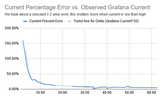
Error Graph from our initial characterization of the current sensor
A few days ago I had my last final exam for the term, so the real work of figuring out how microcontrollers actually work could begin. After bouncing around a few of my existing projects I decided to characterize the ADCs on my STM32 F031K6T6 and ESP32-WROOM-32D to get a better understanding of how to use them and learn more about how they work along the way.
All test data can be found here.
My code can be found here, if you look through previous commits you’ll find earlier test code I wrote for this project.
Initial Testing
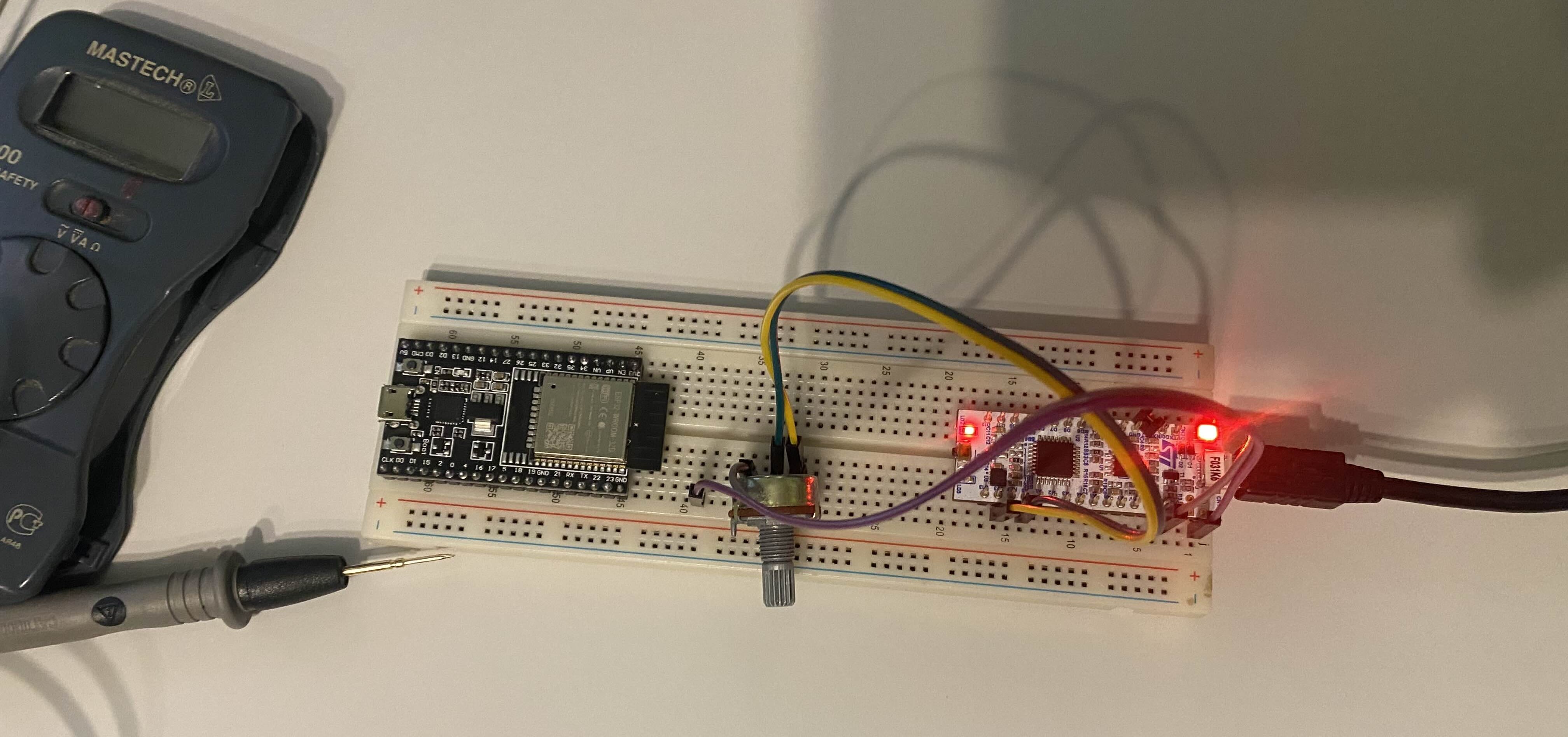
My Initial Testing Setup
I initially wanted a graph of ADC voltage vs. True voltage (as measured by a multimeter) for both microcontrollers. Both have 12-bit SAR ADCs so this testing is applicable to the work on the UBC Solar battery pack. I used a potentiometer to vary voltage between 0-3.3 to get a full range of values. I have no power supply (yet) so I must work with the tools I have. It doesn’t look like the potentiometer introduced much error when comparing these results to those later in testing, it only introduced some noise.
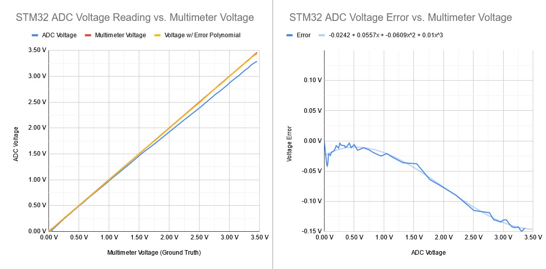
Blue Line = ADC Observed Voltage, Red Line = True Voltage (what we expect), Yellow Line = ADC Voltage plus Error Polynomial
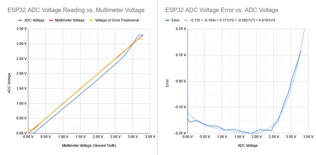
Blue Line = ADC Observed Voltage, Red Line = True Voltage (what we expect), Yellow Line = ADC Voltage plus Error Polynomial
The shape of the ESP32’s ADC voltage graph perplexed me because it appears the first value it observed was 0.14V, and it stopped at 3.18V. Some googling & talking to Grok showed that below 0.1V or above 3.1V the ESP32’s ADCs are not accurate. In the UBC Solar battery pack, we give the current sensor a 1.8V reference voltage to offset the readings. So, we are right in the middle of the accurate range of the ESP32’s microcontroller. STM32 chips have a similar range in which they are meant to operate accurately.
With the ADC observed voltage and the expected voltage, I fit a polynomial to the error using Google Sheet’s built-in function and plotted the voltage + error polynomial on the graph. Note that I didn’t redo the test here with the error polynomial applied in firmware, I just added it to the spreadsheet values. With the error polynomial applied, the STM32 and ESP32 ADCs became accurate to within 0.01V in most of the range (0.5V - 3.0V). The reason this range doesn’t exactly match the expected 0.1V - 3.1V range that the ESP32 chip should be accurate in is because of improper application of the error polynomial, I should have deleted values that are outside the range I want.
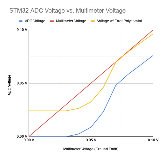
Zoomed in view of the STM32 ADC Voltage vs. True Voltage
This zoomed-in view of the same STM32 ADC Voltage vs. Multimeter Voltage graph from above shows a strange non-linearity point in the graph. Above a voltage of 0.07V, we get a mostly linear error. However, below this, we see this strange non-linear exponential-looking part of the graph. I don’t understand Electrical Engineering or Physics at a low enough level to describe this, but it tells us that the reasonable lower range of the STM32’s ADC is 0.07V.
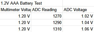
Testing with a 1.2 V Battery
I also tested with a 1.2V AAA battery to ensure that the potentiometer was not an issue and got results that were similarly inaccurate. These results also had a lot of noise. Note that I converted the ADC Reading into a voltage in the spreadsheet with the formula Voltage = (ADC Reading / 4095) * 3.3. This assumes the reference voltage is 3.3V and converts the ADC reading assuming the conversions: 0 = 0V and 4095 = 3.3V.
Using the esp32-adc-calibration Github repo
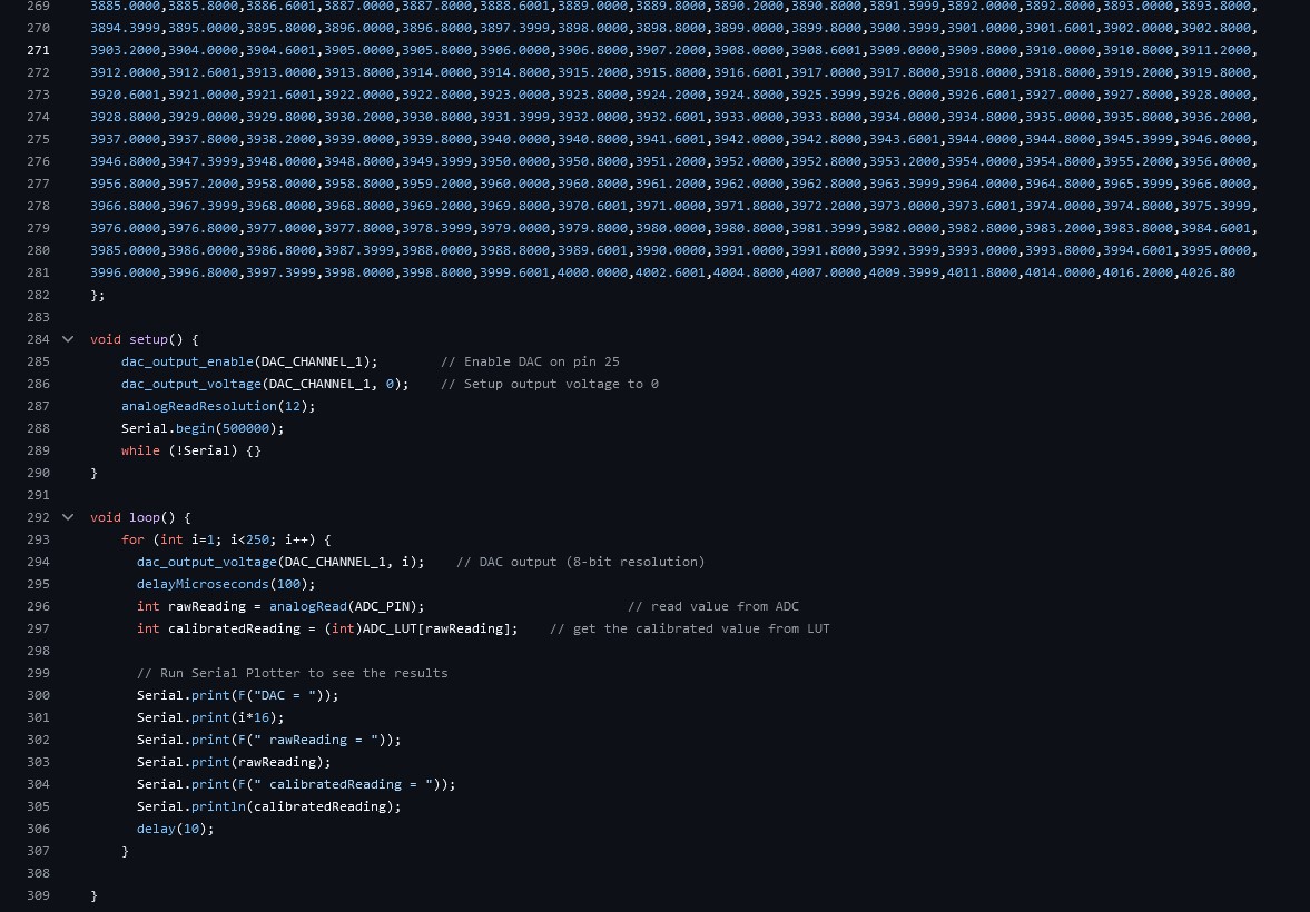
This is the code from the Github repo I used, notice the line count and the massive array at the top that stores the lookup table.
In researching I found this Github repo that uses the ESP32’s DAC (Digital to Analogue Voltage Converter) to get the chip to characterize itself. If you have a known voltage output from the DAC, you can pipe this directly into the ADC and find your error in firmware instead of on a spreadsheet. This Github repo then takes the error values and feeds them into an Arduino .ino program (ESP32’s can run using the Arduino IDE) to get a lookup table of errors. Essentially, it records 256 values and for each range in between them, it calculates the error. With these ranges, you can use them as a lookup table where you input your ADC value as a key and get the expected ADC value back for that particular ADC voltage.
This lookup table approach required 16 KB of flash memory on the ESP32. If we really wanted to do this on the UBC Solar battery pack we could shrink the lookup table to 128 values and probably have enough flash left over for the other programs. However, this is still a very stupid idea. We aren’t software devs that can throw memory and compute at all of our problems.
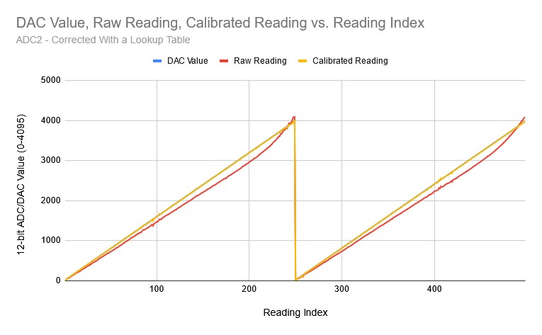
Blue Line = DAC Output Voltage, Red Line = Unadjusted ADC Reading, Yellow Line = ADC Reading Adjusted with Lookup Table
The shape of the error looks very similar in this test and the calibrated reading is spot on with what we expect. However, I later found out that the output of the DAC cannot be trusted. When testing with a multimeter, its output was inaccurate in a similar way to the ADC. So, this kind of test where you use the DAC to calibrate the ADC is not possible on my ESP32 chip.
I initially wanted to write my own self-calibration script for my STM32, but after realizing the DAC may not be trustworthy and the fact that unlike UBC Solar’s STM32 chip mine doesn’t have a DAC, I decided to abandon this idea. If on Solar we find that the DAC on our chip is trustworthy, this could be a good way to calibrate the ADCs on any of our boards, not just the ECU (Elithion Control Unit) in the Battery Pack.
Testing Attenuation
In the README for the esp32-adc-calibrate repo, the author mentions that reading the ADC Calibration documentation is a good first step before implementing the code. I read it and found the esp_adc_cal_characterize() function that allows you to set the attenuation, bit width, and other parameters for either of the two ADCs on the ESP32-WROOM-32D. There’s no automatic ADC calibration, but I could set parameters and record the results.
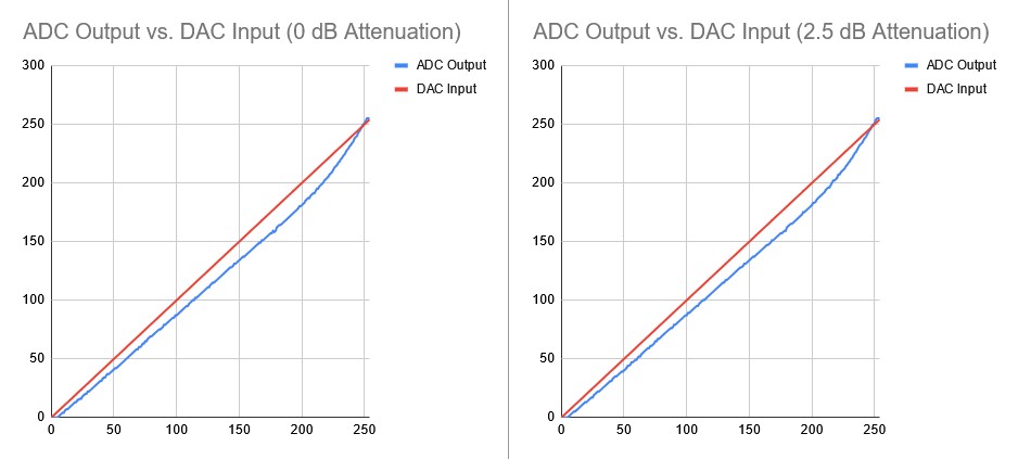
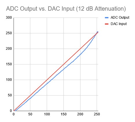
Little difference was found between all the attenuation values.
I wrote some firmware inspired by the Github repo above that automatically tested the ADC given a range of DAC values. This was before I found out the DAC is not trustworthy to output specific voltages within ~0.1V in most of the range while I needed ~0.01V precision.
With that firmware, I automatically tested the attenuation values of 0 dB, 2.5dB, and 12dB to see if there was any difference and found none. Attenuation is essentially signal boosting, and I was using a small jumper cable, so it made little difference. However, when swapping out the jumper cable for a short paper clip I found that the noise was reduced. When I get into designing PCBs I’m sure I’ll understand this phenomenon better.
Raw ADC Values Testing
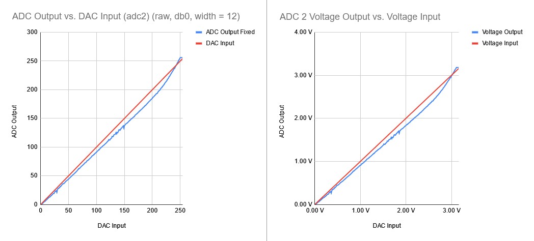
I tested ADC 2 with lower-level functions and found little improvement.
Looking further into the ESP32 documentation, I found lower-level libraries that can be used to get the raw ADC values directly instead of interfacing through the Arduino library. I wrote a quick function to convert this raw value into a voltage and tested it using the same “DAC voltage into ADC” strategy as before. I found no difference between my own custom conversion function and the Arduino library’s analogRead() function. I also tested the second ADC on my ESP32 and found little difference in the results compared to the first ADC. However, the second ADC was accurate down to 0V while ADC 1 was accurate down to 0.08V.
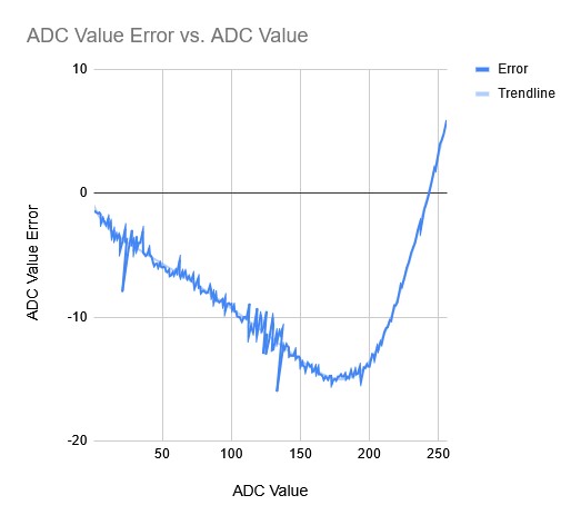
With the graphs above, I got the error graph and fit a Polynomial (trendline) to it.
I then got the error for ADC 2 in raw bits. Instead of converting to voltages and then getting the error, I skipped that step and got the error in raw ADC values between 0-255. This isn’t keeping with the ADC’s 12-bit range because the DAC only goes to 8-bits, so I was limited to 8-bits of precision. I then fit a polynomial to the error and got the error graph above. The error was very similar to earlier testing, so nothing I had tried fixed the problem and mostly served as an exercise in understanding how to use the ADC on my ESP32.
Discovering the DAC was Imprescise
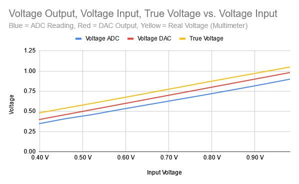
I tested the ADC and DAC with a multimeter and found that all the values differed.
During the previous round of testing with the raw ADC values I decided to take out a multimeter and get a ground truth value for the voltage. I discovered a discrepancy between the DAC’s expected output voltage and the voltages the multimeter was showing. I tested it on a range of values between 0.4V and 1.0V and found a difference along the entire range - this is the data charted above.
Above you can see the True (multimeter) voltage, what the DAC thinks it’s outputting, and what the ADC thinks the voltage is. All of these values differ by a significant amount (~0.5 - 0.1V). This means a self-calibration is not possible because the DAC’s specified output and what it actually outputs are not equal.
Conclusion
To properly characterize and calibrate the ADC I would have to get the graph of ADC Value vs. True Voltage (As observed by a multimeter) and fit a polynomial to it in the range that the ADC error is mostly linear (0.1V - 3.0V). This is probably the solution to the issue we’ve had with the UBC Solar battery pack. However, if we find that the DAC on our chip is trustworthy, writing some firmware to automatically calibrate the ADCs on all of our boards would be a great way to ensure we never have this issue in the future on any boards.
This solution looks very obvious in retrospect, but it took a while to understand the systems and issues from a fundamental level to come to this conclusion with a high level of certainty. I’ve learned a lot about this project and there’s even more to learn about why these ADC errors emerge in the first place.