Rewiring a 240V Kiln and Producing Calcium Oxide
Intro
Two weeks ago I applied to Terraform Industries and spoke to Casey Handmer. His advice was that I gain more experience through projects and that reading textbooks and going to class doesn’t really teach you anything. About half an hour after I spoke to him I decided on taking on direct air capture of CO2 through the calcium looping process as a project.
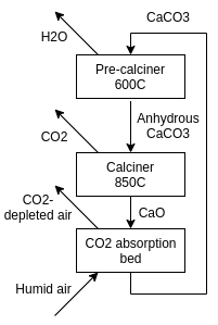
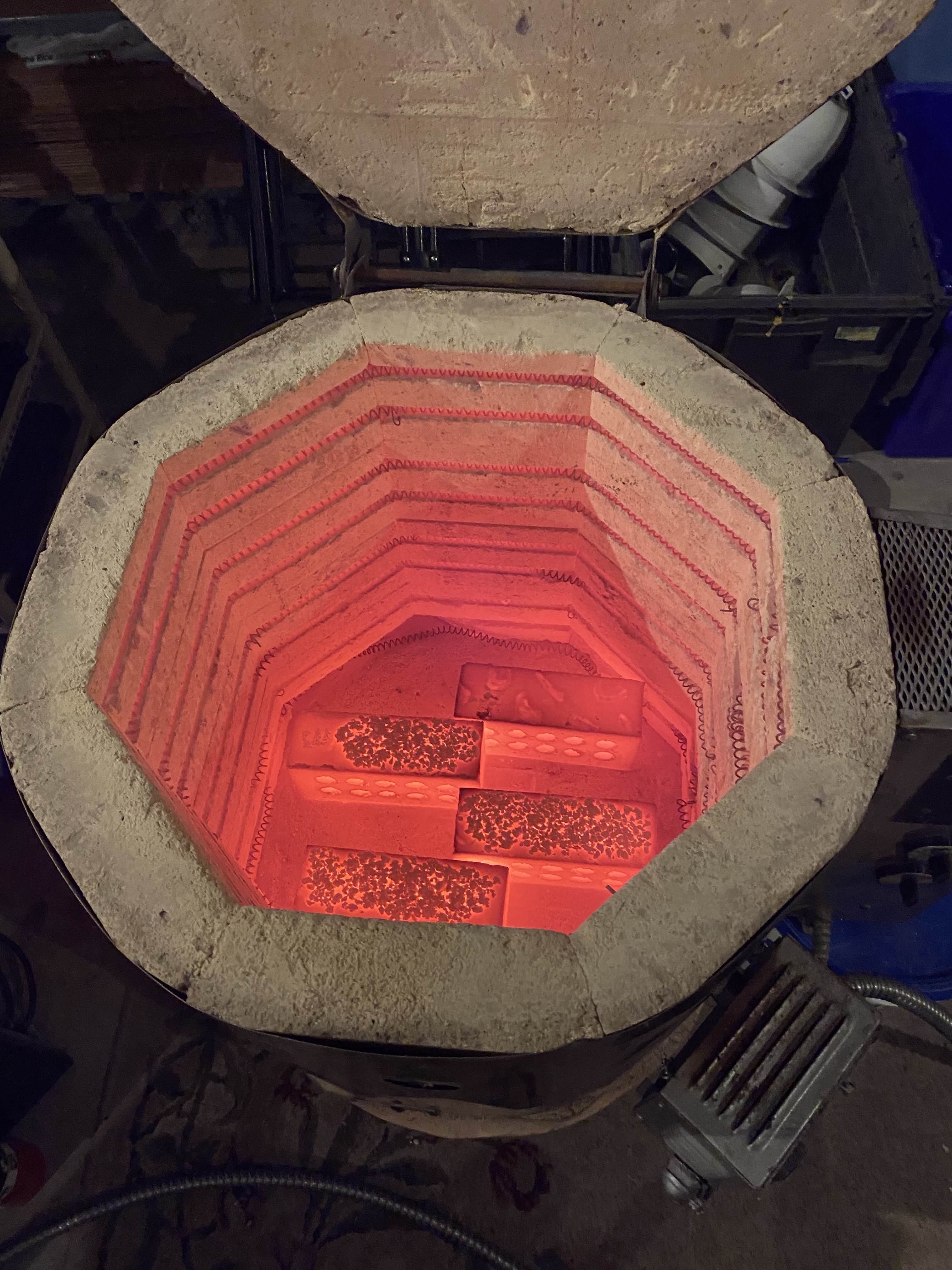
Terraform industries is using this process to produce carbon-neutral CH4 and CH3OH from sunlight and air. The stoichiometry of the calcium looping process is shown above. The calcination step is done at ~850-900 C and produces Calcium Oxide (CaO) and is what I approached first (can’t have a CO2 absorption bed without CaO to start with).
My project notes are available here. If you can parse them, there are more details in there.
I’ll try to keep this post short and just get into fun anecdotes in a few parts of the project.
Theory of Operating + Wiring
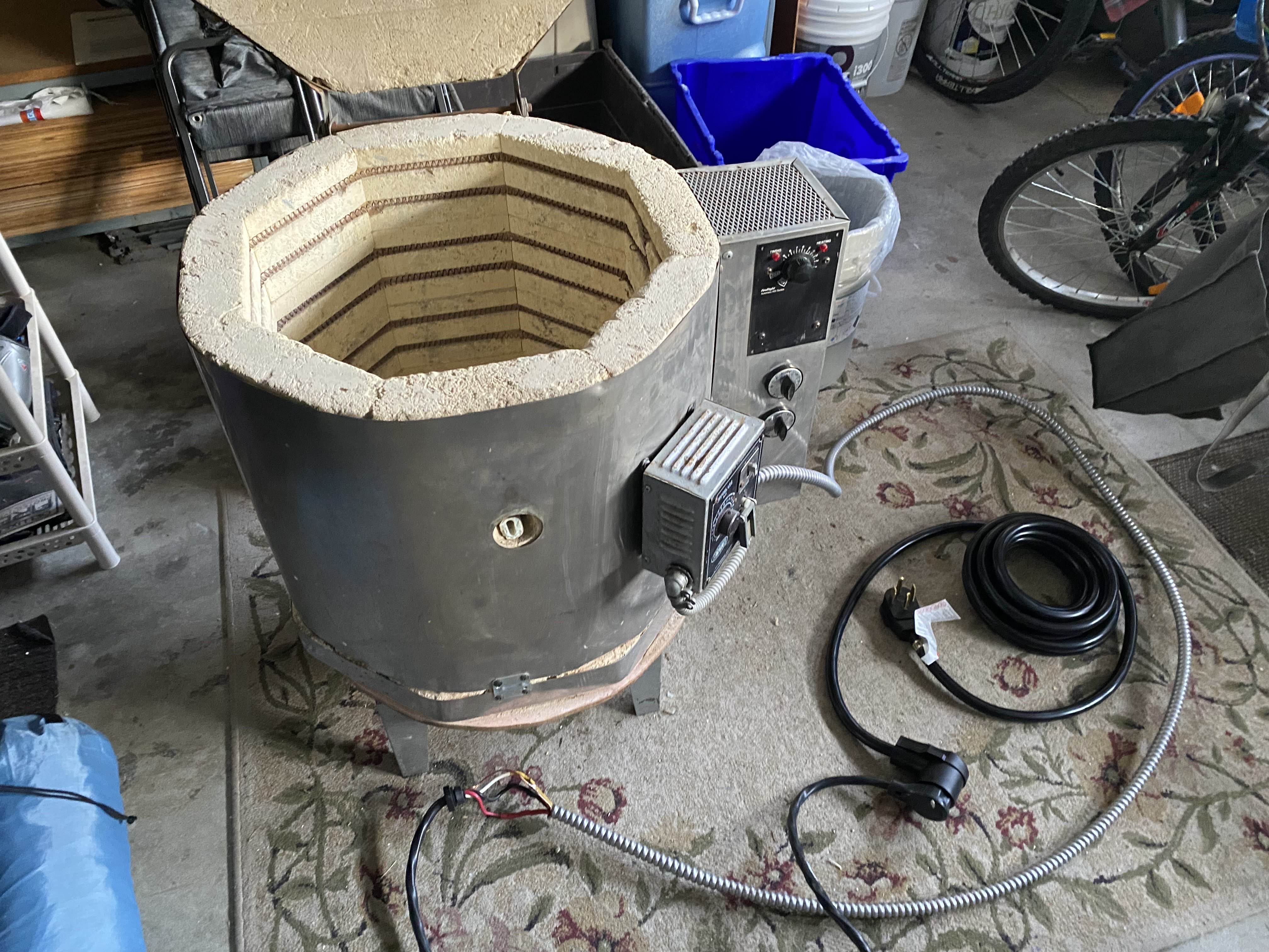
I bought a $300 kiln off Facebook Marketplace with a missing power cord and a couple broken elements. In the interest of moving fast on this project I didn’t do much research before this and jumped straight into serially solving all problems with the kiln.
In any project there are always a finite number of problems you have to solve, so you can move very quickly by attacking the problem directly in front of you at full force, solving it, and moving onto the next one.
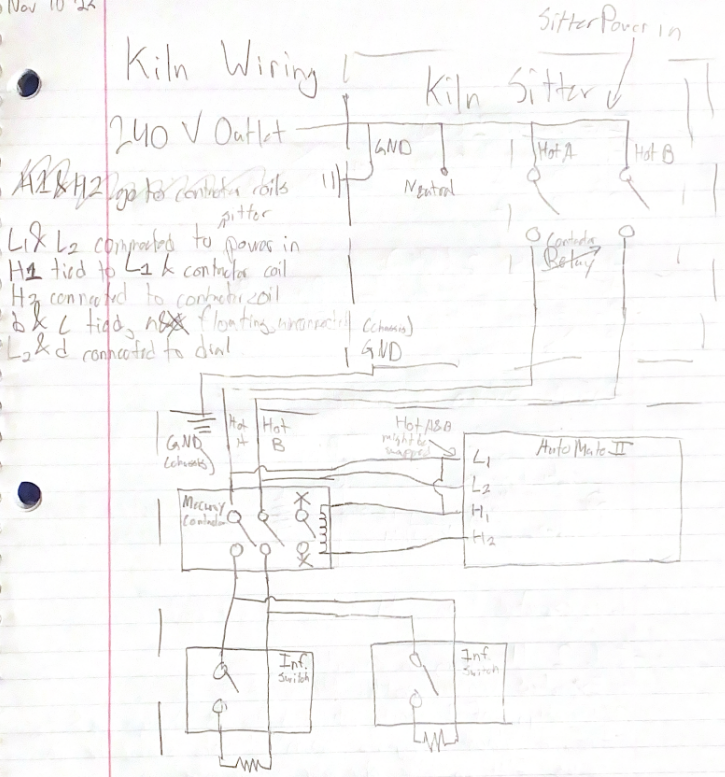
The first step was to understand the wiring of the kiln. My quick wiring diagram is shown above.
There are three main components:
- Kiln Sitter (240 V input, makes sure you don’t accidentally leave it on all night)
- Element Control Box (Several contactors and switches control current flow)
- Heating Elements (Resistors)
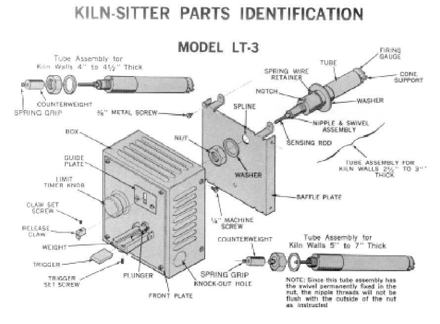
LT-3 Kiln Sitter
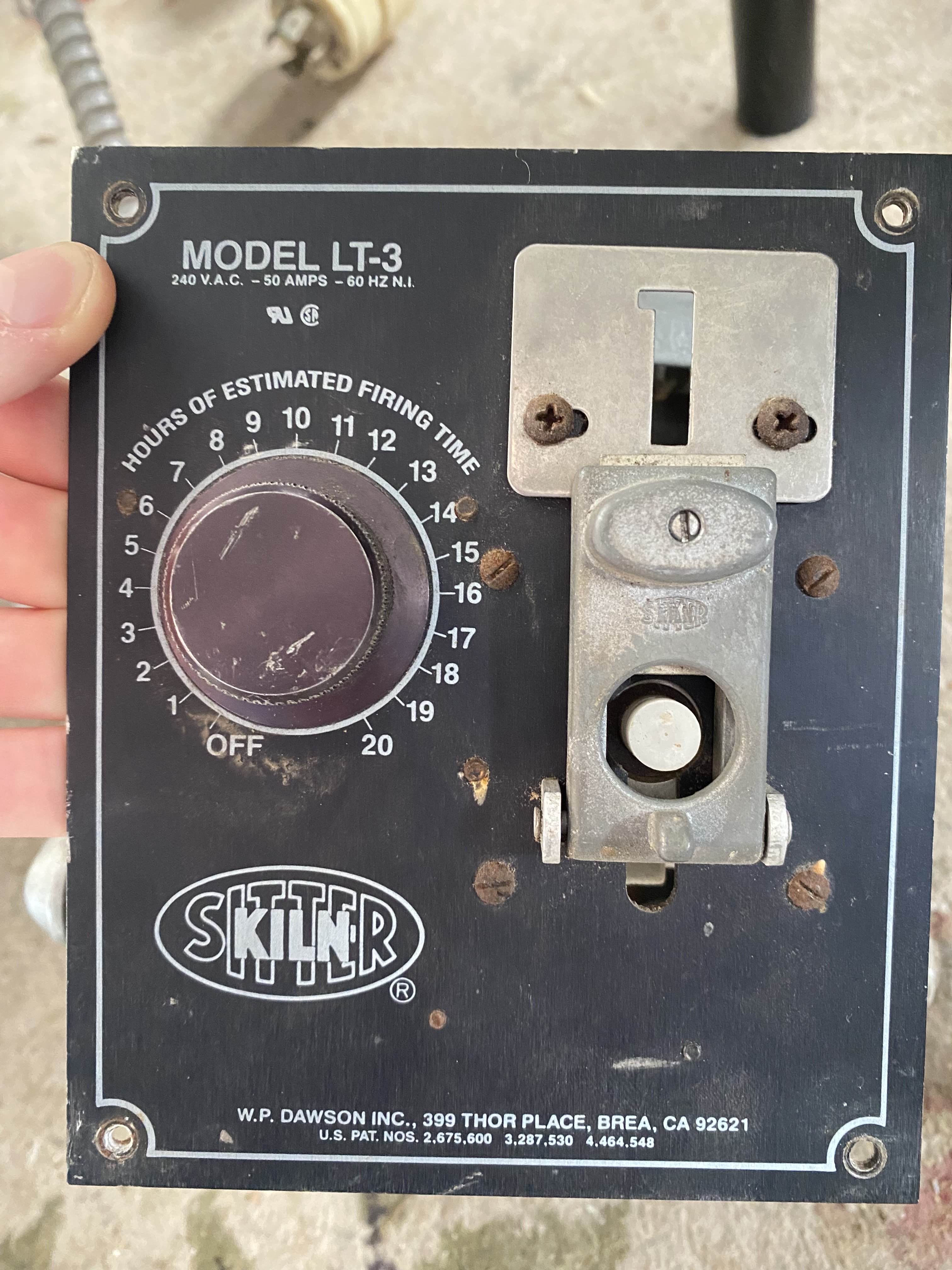
The LT-3 kiln sitter contains a relay (with an unknown part number) that connects both 240 V phases to the element control box. This relay is the first switch in the kiln.
The Kiln sitter has two methods of turning off the kiln:
- A sensing rod deforms with temperature, and at a critical temperature it releases a weight (visible in the image above) that hits the relay armature and opens it.
- A 4 RPH (revolution per hour) synchrotron rotates and when it hits 0 hours, a spring is released that hits the relay armature and opens it.
The ceramic tube containing my firing gauge cracked in half when I was removing the kiln sitter, and the sensing rod has degraded over decades and now doesn’t hold the weight up, so it wants to enternally keep the relay open. So, I had no way to use this safety mechanism.
The synchrotron does seem to work, and it’s required that it’s turned to >0 hours for the relay to activate.
Element Control Box
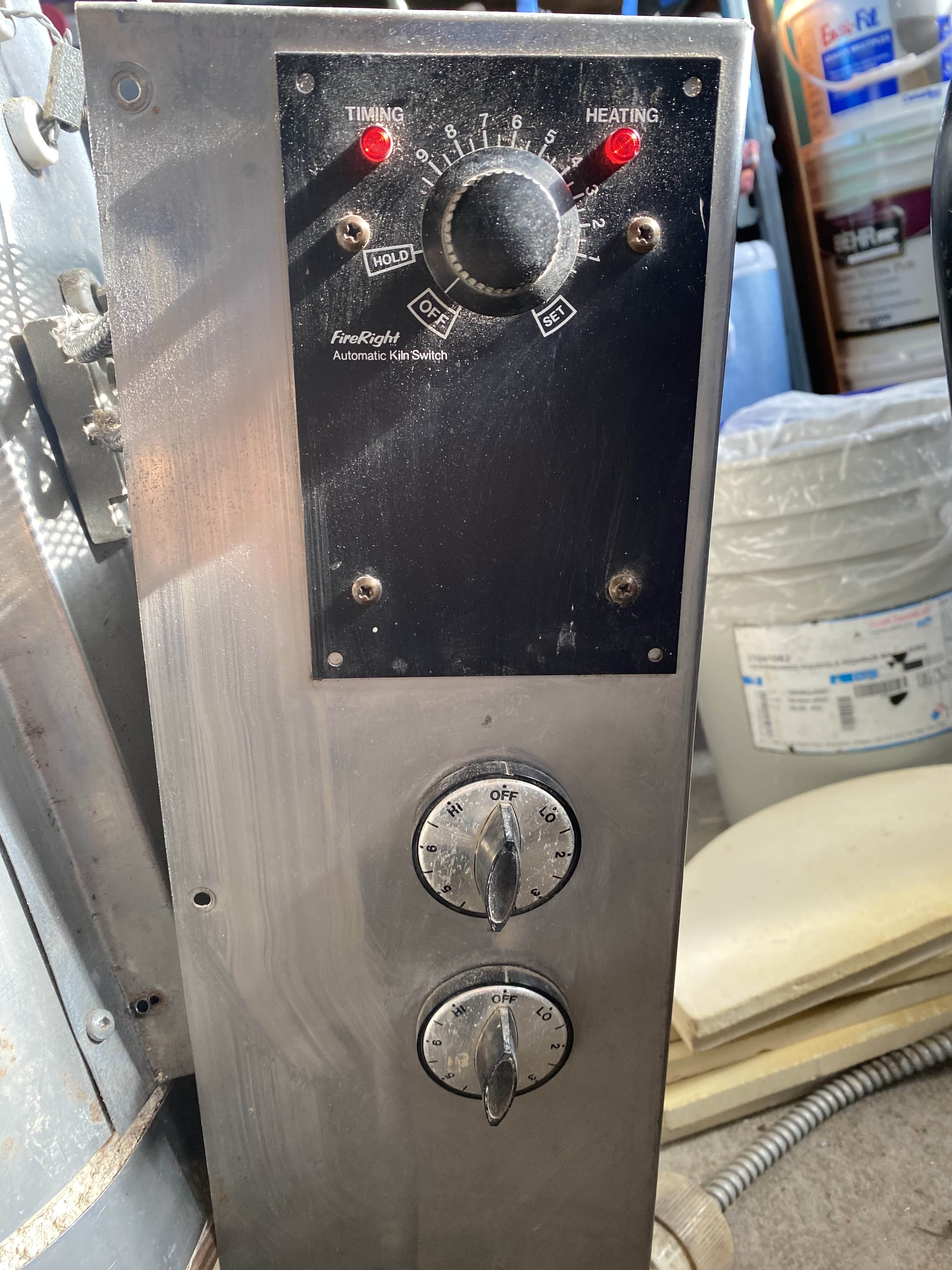
The element control box has 3 primary components:
- AutoMate II PCB (For a basic temperature profile)
- Infinite Control Switches (Maintain a given current, these are fascinating more on them later)
- Mercury dipped contactor (Again, a very fun concept)
The wiring was shown in my sketch above.
AutoMate II PCB
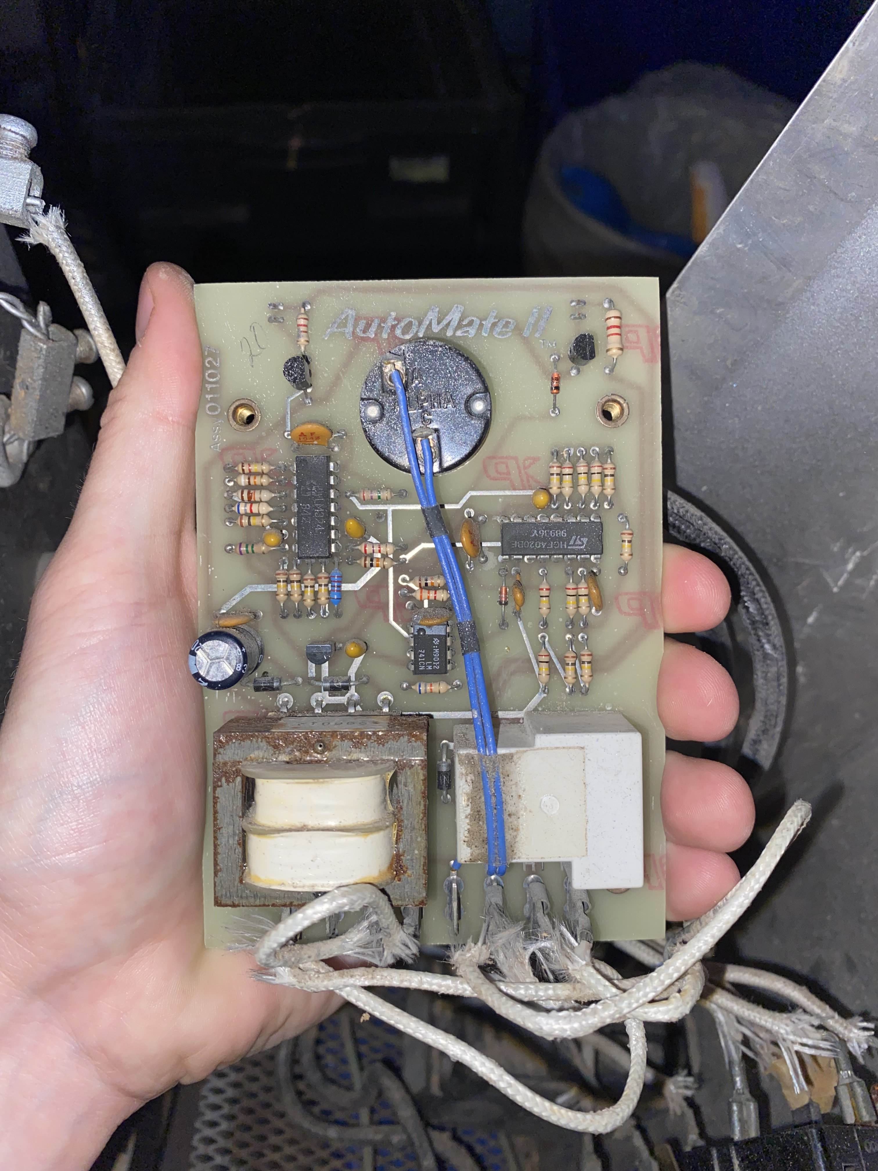
This PCB is on the other end of the black control panel shown in the element control box image in the previous section.
It takes in both phase A and phase B, steps this down into some sort of logic voltage, then outputs a PWM signal to the primary mercury contactors.
It scales the duty cycle over 0-10 hours so you can get a sloped temperautre profile. Note that all control in this kiln is done by current, not temeperature. Not a thermocouple in site, so you’ve just got to guess what temperature a 60% duty cycle will get you to.
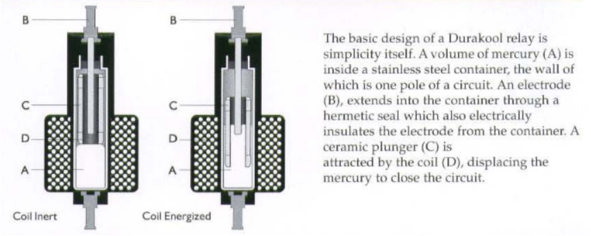
Mercury Contactor
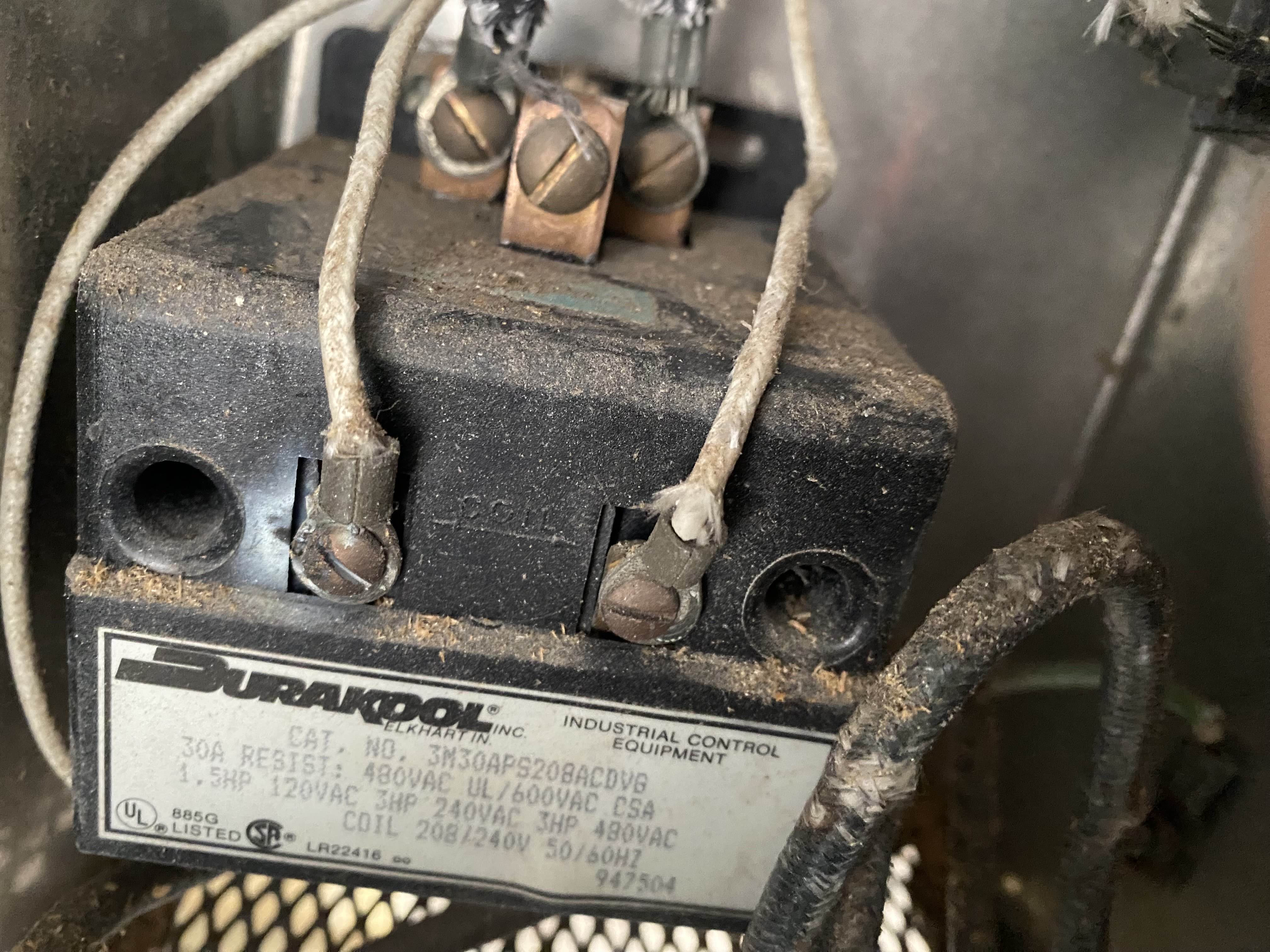
This is the primary contactor in the element control box. After the kiln sitter relay, this is the next switch in the path of current flow.
Because the AutoMate II PCB needs to control this contactor with PWM, it needs to be able to tolerate very many cycles in its lifetime. So, it uses an armature driven by a 240 V AC solenoid which is dipped into mercury as a conductor. This results in less mechanical wear that armatures hitting each other, liquids are nicer.
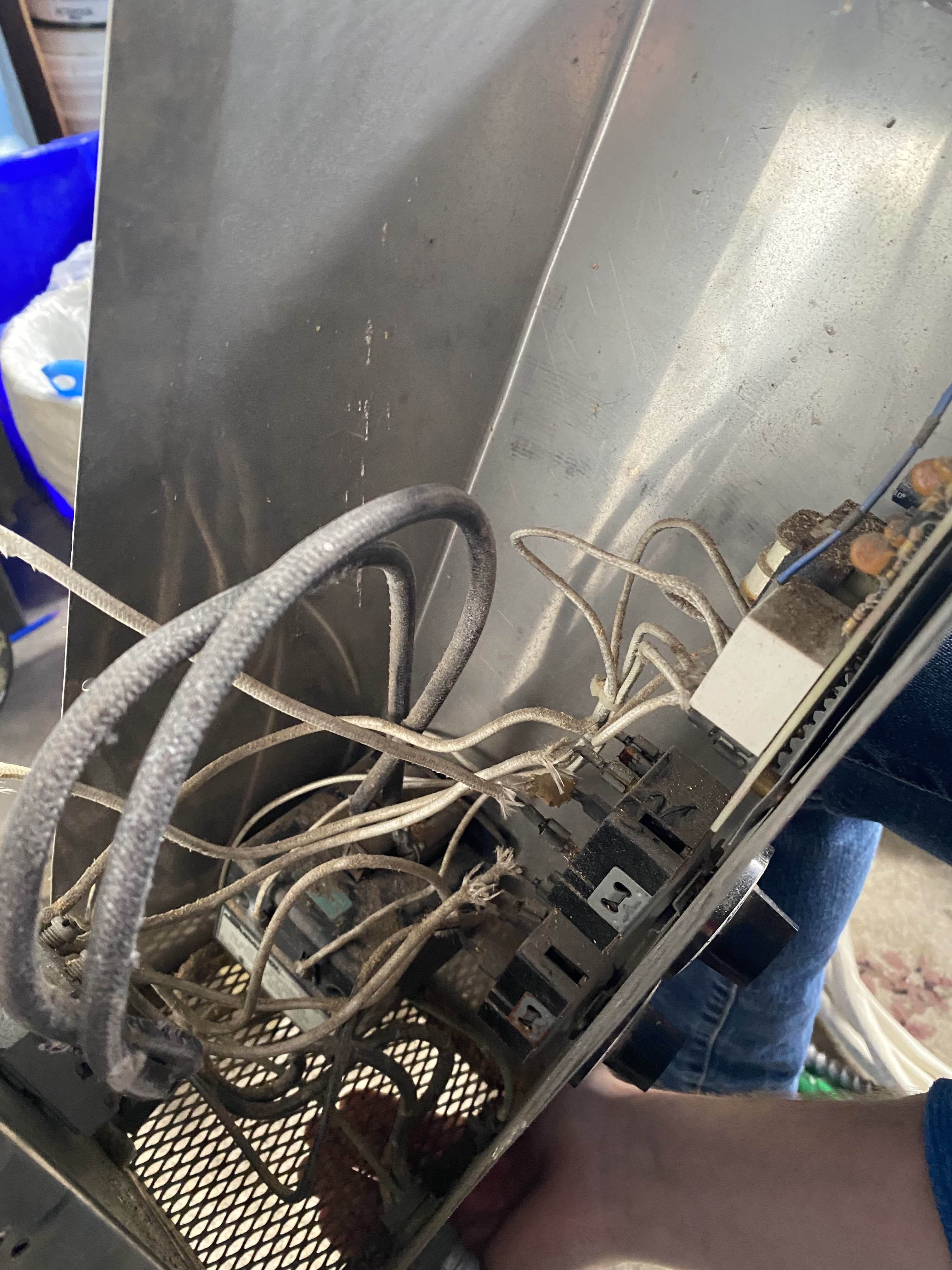
Infinite Control Switch
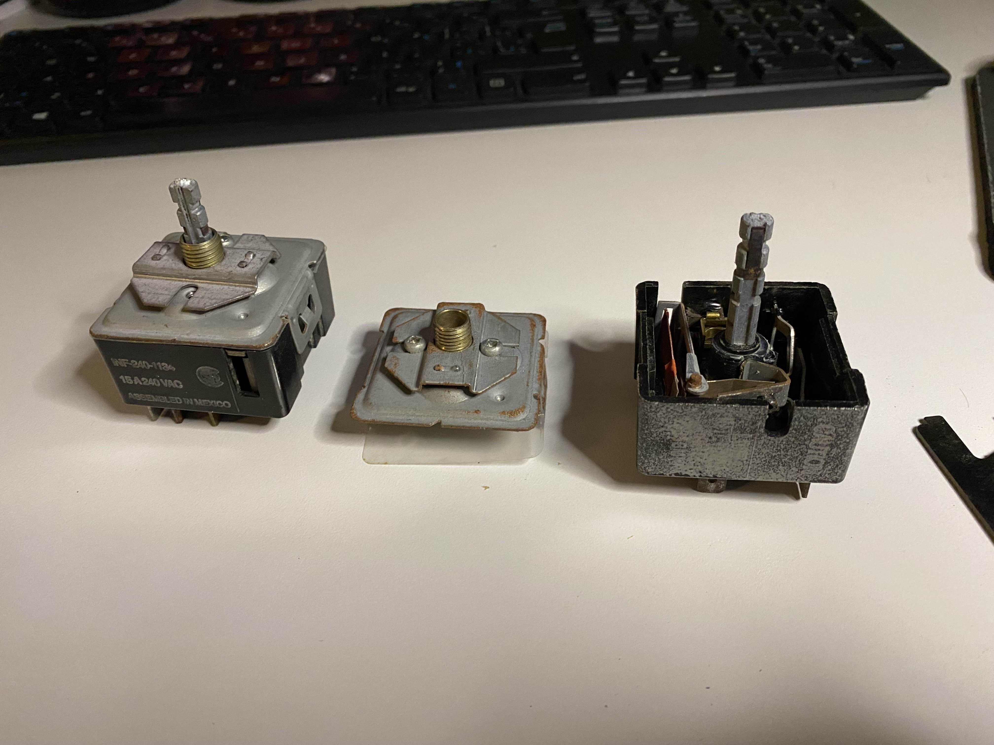
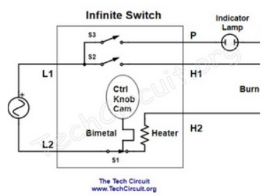
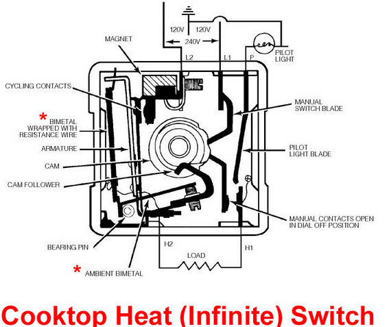
An infinite control switch allows for a primitive hardware-based form of PWM to control net current flow into a device.
A small bimetallic strip is connected to the armature of the switch. When this strip is heated, it deforms such that the armature is released from its contact and current flow is broken. Then, it cools back down and reconnects.
The bimetallic strip has a resistive heater wrapped around it which is in series with the primary current path.
Depending on the initial force on the bimetallic strip, the point at which the armature opens can be adjusted. For example, the strip has to deform more to open the strip if it’s prestressed with 10 N versus 5 N.
The initial force on the strip is adjusted with a stepped CAM shaft that the user can rotate.
This way, you can manually set the initial force on the bimetallic strip, and hence the temperature required to open the switch, and hence the duty cycle of the switch. (This part might not be quite true, it’s dependent on the the rate of heating and cooling).
Rewiring
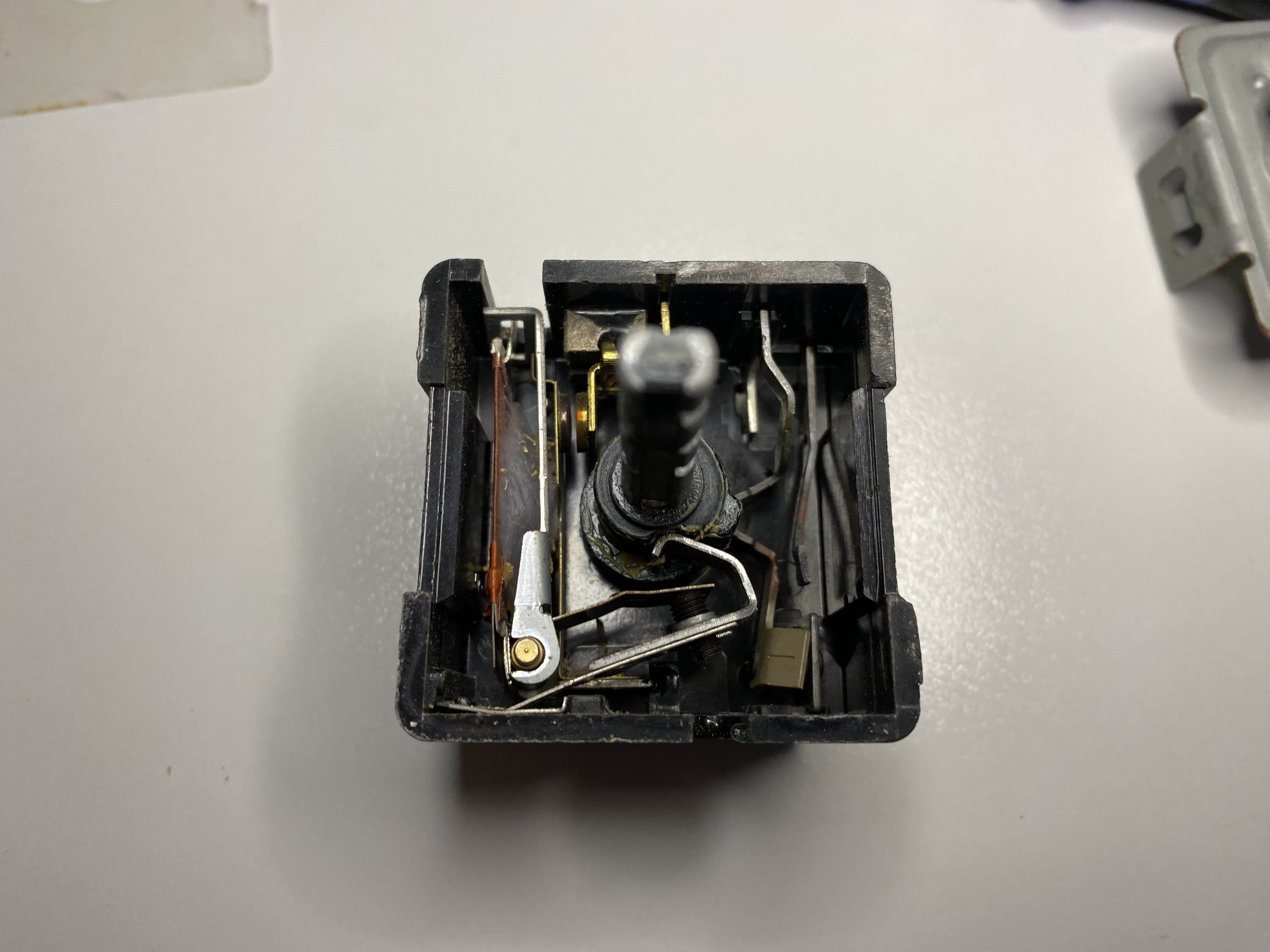
If you look closely at the image above you’ll find a spider web on the left side of the infinite control switch. It turns out mechanical switches don’t like being left outside for decades (one part was labelled 1995 on the kiln), so I had to open the infinite control switches to return them to an operational state.
They were too far gone to operate as primitive PWM-controlled switches, but I could still use the secondary side of the switch as a regular switch (See the second figure in the previous section which shows a two paths for current to flow).
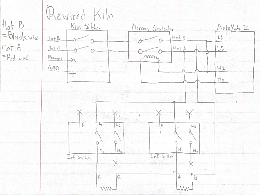
Above is a schematic of how I rewired the kiln. Essentially, the major difference is that I skipped the L2/H2 “PWM” side of the infinite switch. Now, only Phase A is being switched and Phase B is always connected to the heating elements.