What I Learned From Other Teams At FSGP 2025
Waterloo
Highlevel Overview
- LTC6811 Slave Board IC
- XBee Radio Modules
- Grafana Telemetry
- 10 Ah custom supplemental battery
- LTC4418 for power distribution (Power Prioritizer like Purdue)
- Prohelion Wave Sculpter 22 Motor Controller
- Duraclick connector for CAN
- Nomura MPPTs
General Notes
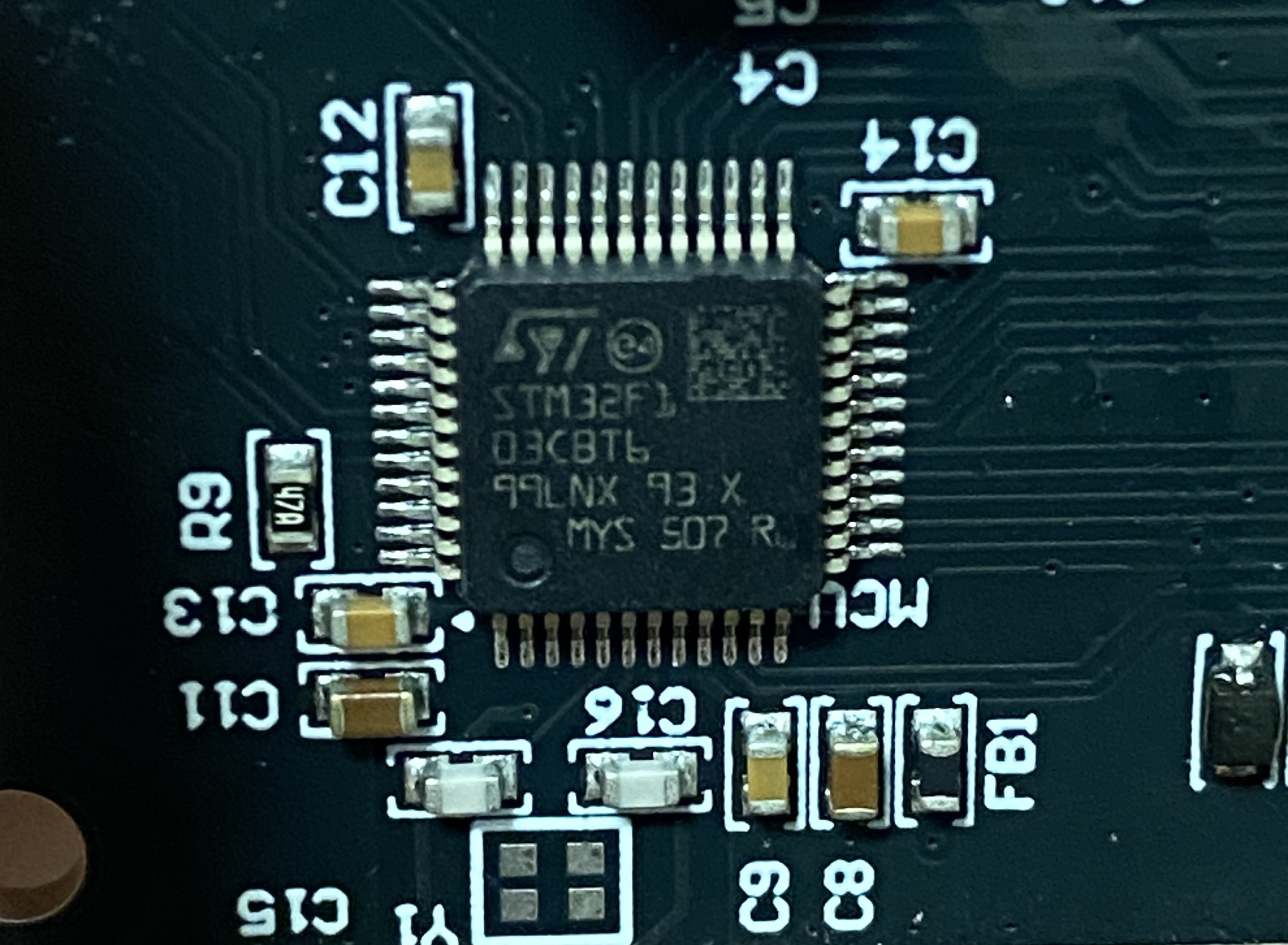
Bootloader & STM32
They have Bootloaders to flash over CAN (I think it was CAN). Mostly because “It’s an easy project for a first year.”
This is also why they want to use STM32F103CBT6’s instesad of the C8’s. The CB has 128 KB of flash memory while the C8 has 64 KB, which is not quite enough space for the bootloader and the application code.
The STM32F103CBT6 is also the same chip that is on our ST-Links.
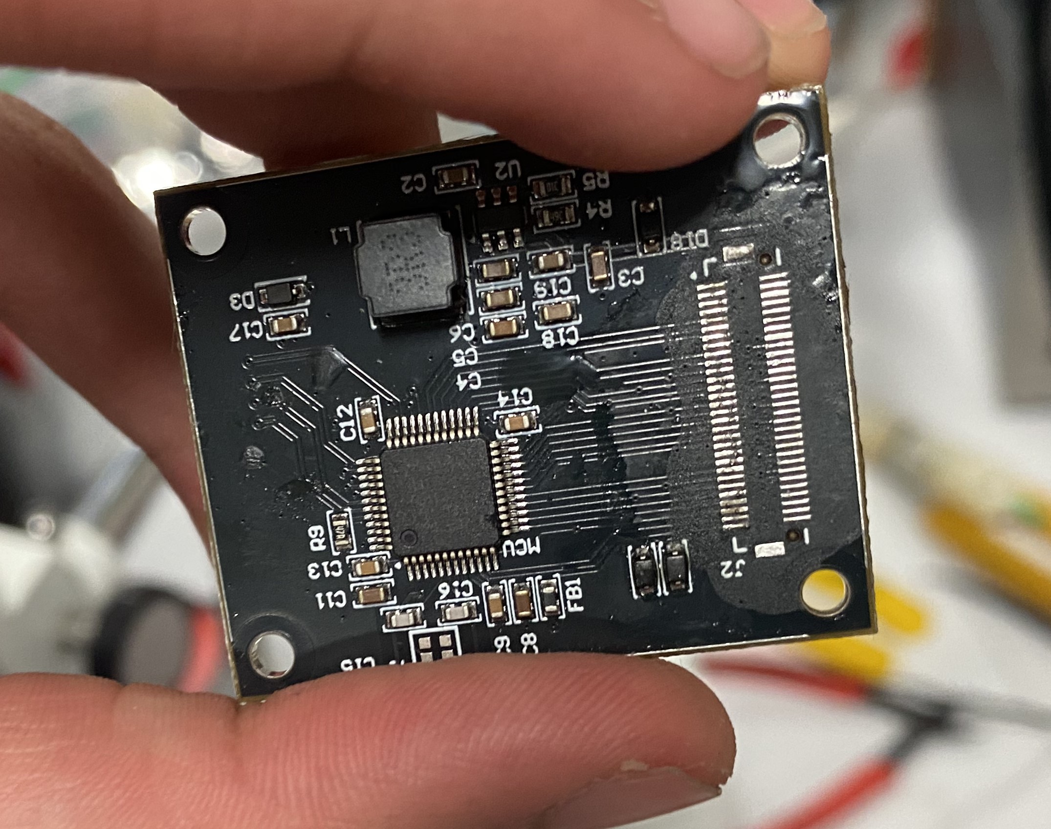
Controller Board
Expanded Image
Expanded Image
MS15’s standard Controller Board.
Waterloo uses a single common microcontroller board for everything. They call it a Controller Board.
They have 4 of these boards in the car:
- Battery Management System (BMS)
- Power Distribution Board
- Console (Driver User Interface)
- Motor Controller Interface
These are relatively small boards and have a few standard components on them. Essentially, they build their own standard microcontroller board suited for their needs.
Each board has output pins (GPIOs, etc.) wired to what looks like a Micro Blade & Beam connector. This specialized connector allows for many connectors in a small form factor.
In the Power Distribution Board section below, you can see how this Controller Board slots into the Power Distribution Board (Look for the Micro Blade & Beam connector and four screw holes). A similar slot exists on their BMS board.
Having Controller boards slot directly into PCBs (Like our DCDC does) allows for a more durable connection. I was originally skeptical of this connector, as I’ve killed many similar ones when disassembling iPhones, but iPhones use a ribbon cable with a similar connector, not a rigid PCB on the other end.
This also allows hot swapping microcontrollers, which is only an advantage if you’re regularly killing microcontrollers, which you shouldn’t be doing.
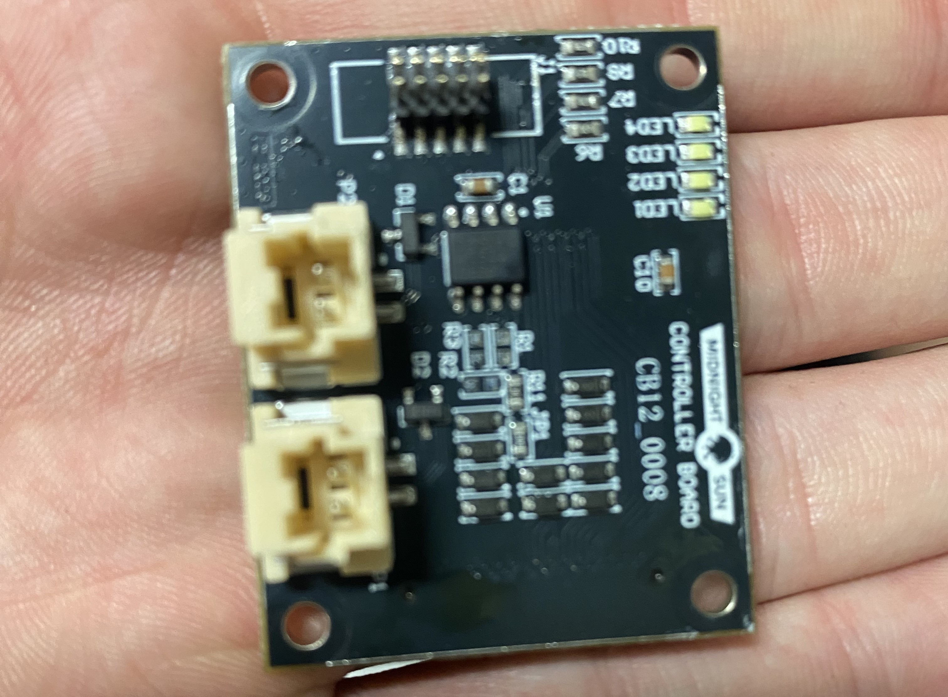
CAN Architecture
Expanded Image
MS15’s standard Controller Board with CAN In and CAN Out ports.
Each Controller Board has a CAN In and a CAN Out port, which allows them to daisy chain the boards together. All boards are connected in series on a single CAN bus. The final board has a termination resistor.
The only issue they’ve had with CAN is low arbitration messages getting dropped. Fairly standard and simple issue.
They use the Duraclick 2-pin connector for CAN.
It seems that Controller Boards are on their own CAN Bus. The Motor Controller is on a separate CAN bus. To communicate with the motor controller, they use a SPI to CAN IC on the Motor Controller Interface Board (MCI). They ran out of CAN peripherals on their Controller Board, so had to use SPI to CAN to communicate with the motor controller.
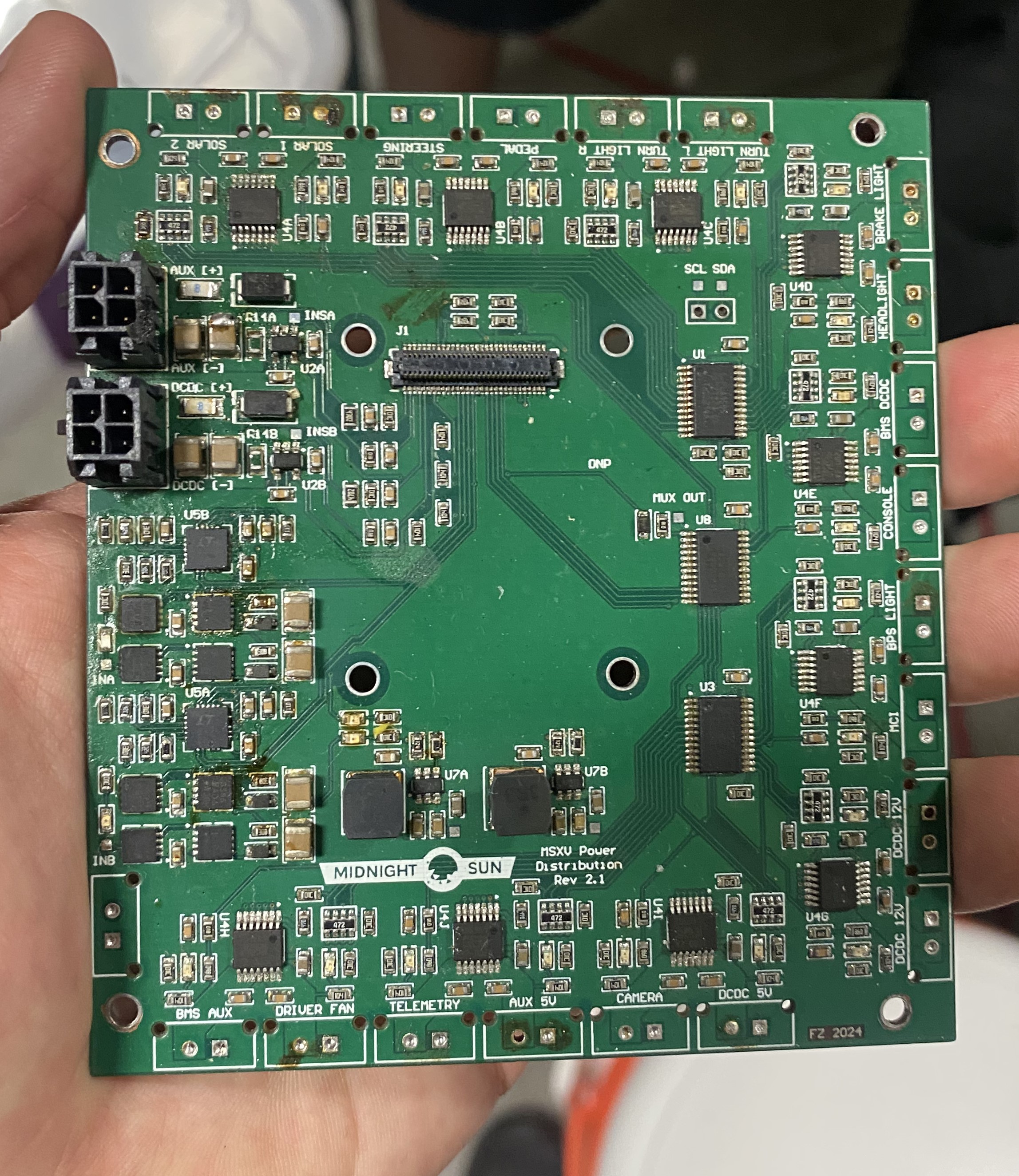
Power Distribution Board
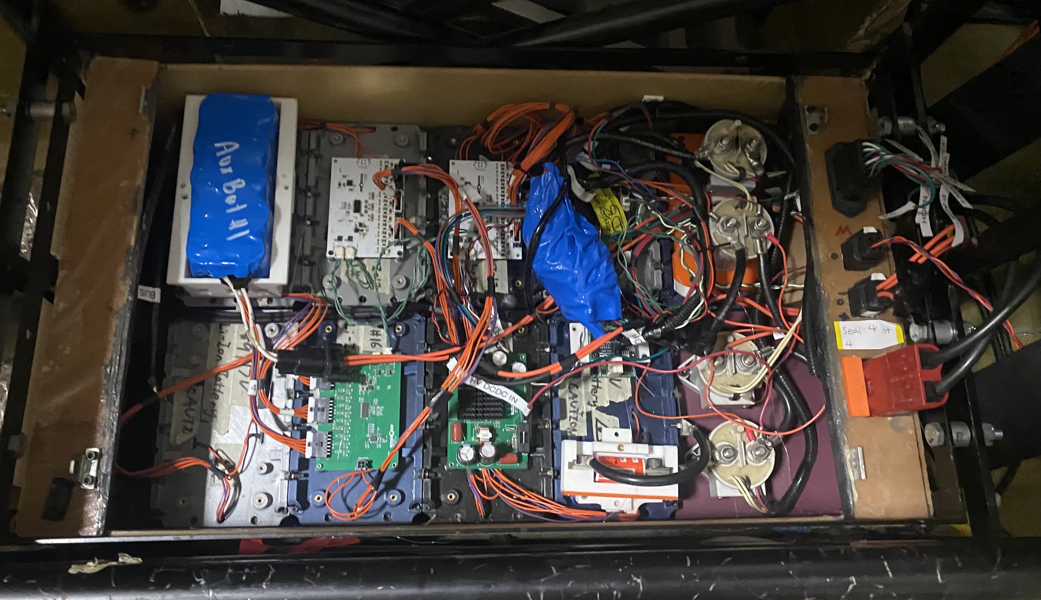
Expanded Image
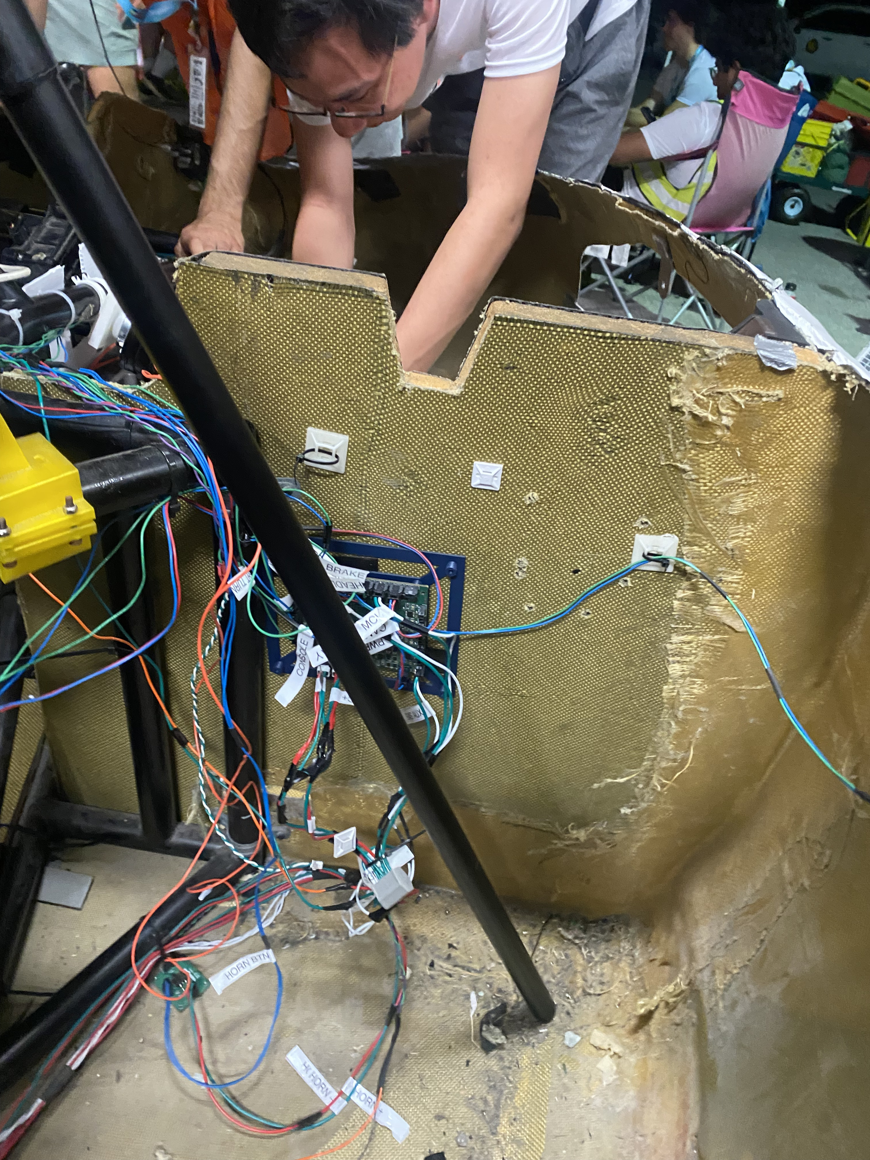
Expanded Image
MS15’s Power Distribution Board.
Midnight Sun 15 has a single Power Distribution Board that lives outside of the battery pack. Standard power connectors enter this board from the battery (Left side of image).
I unfortunately didn’t get the names of ICs / their purposes, but someone on Midnight sun who worked on this board can certainly be contacted for more info.
This Power Dist Board also powers the BMS. This presents an issue because the Auxilary Battery (10 Ah and custom built) is required for initial startup and it lives in the battery. So, a wire from the supplemental goes to the Power Dist Board, then back into the battery to power the BMS.
The Waterloo guys described this themselves as convoluted and suboptimal, so having a Power Distribution Board in the battery (or as part of the enclosure) is a good idea.
10x Nomura MPPTs
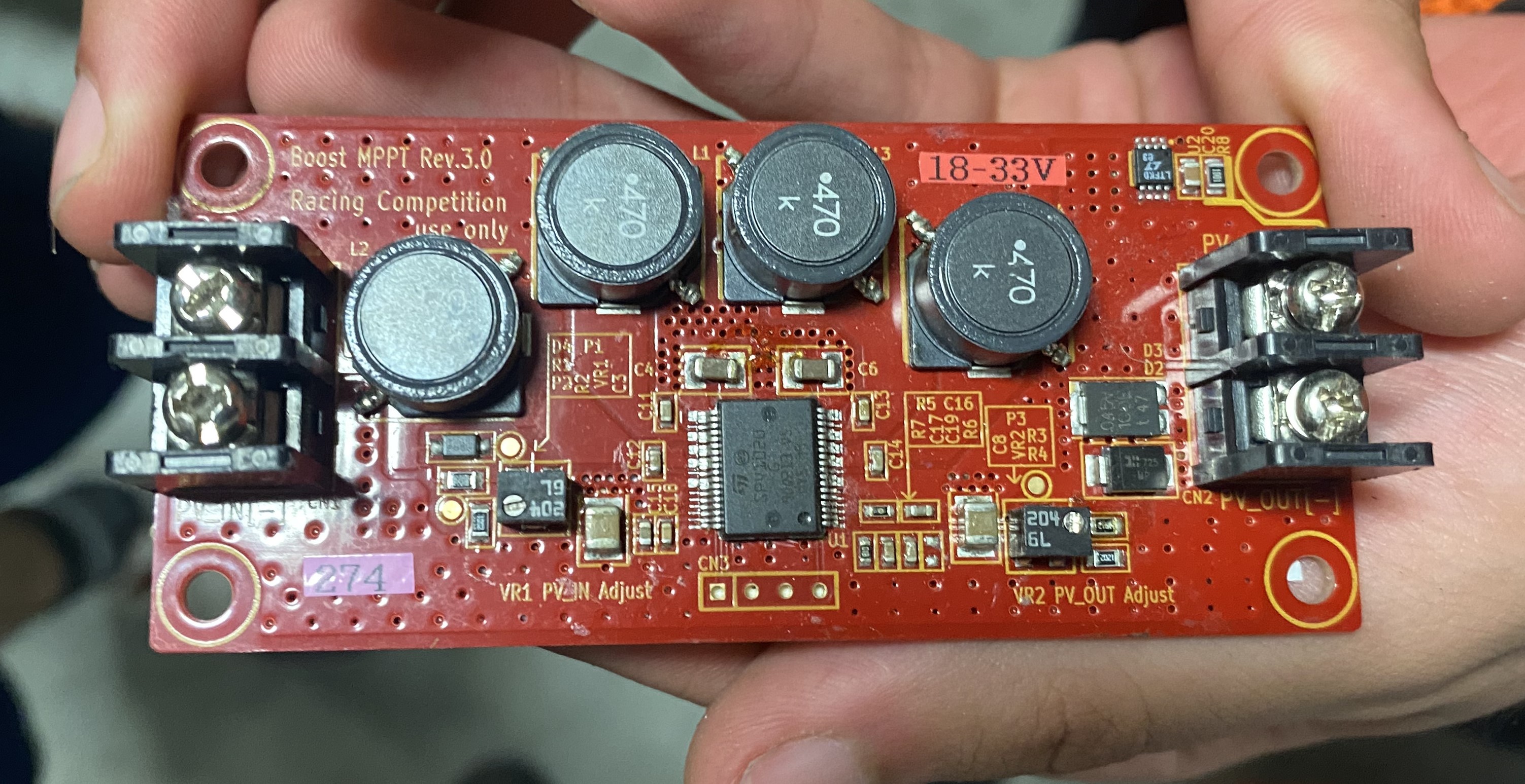
Expanded Image
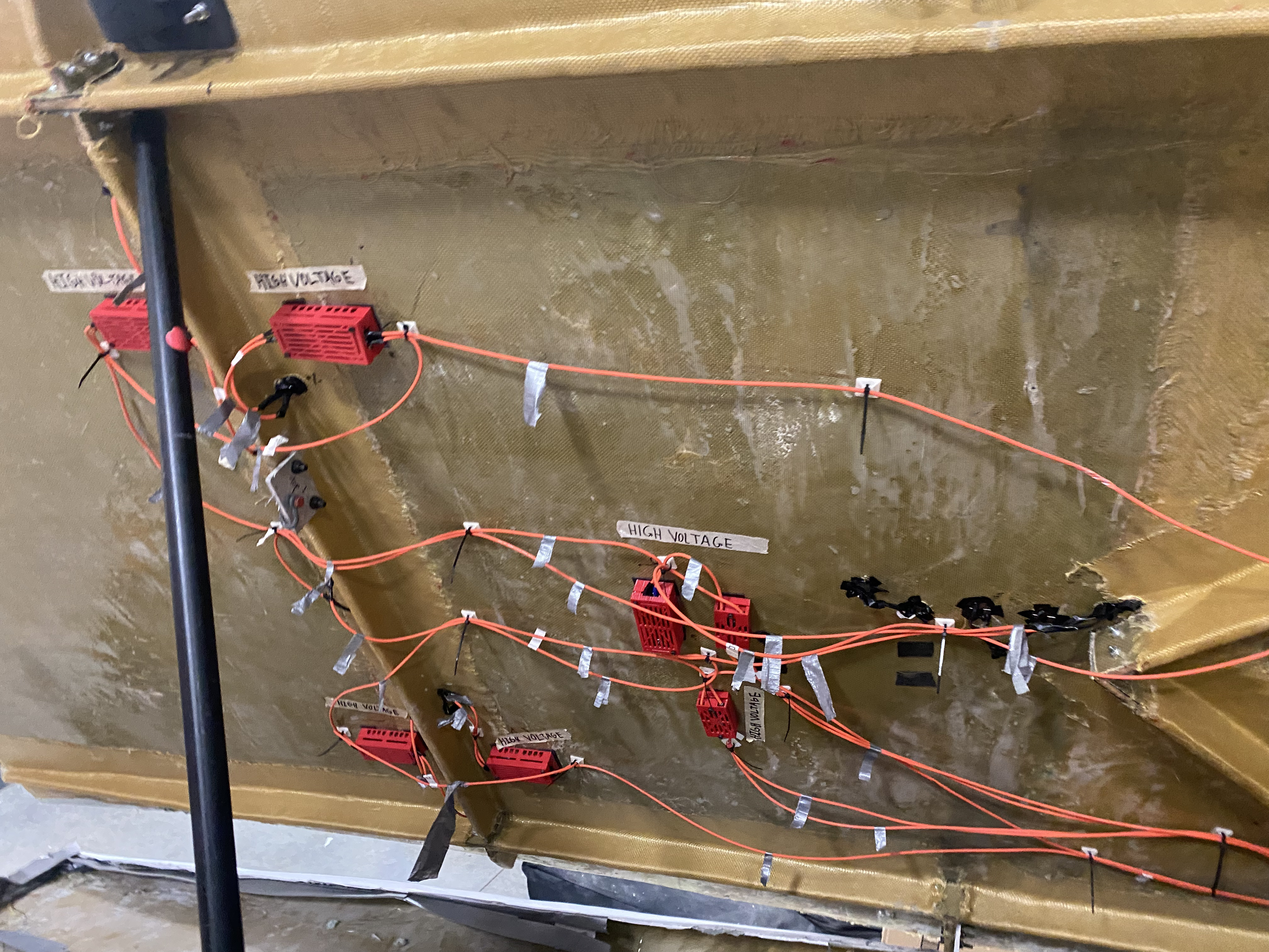
Expanded Image
Bottom of MS15’s top shell showing MPPTs and arrays in series.
Mightnight Sun 15 uses 10 Nomura MPPTs, with 5 each in 2 strings.
They wire them such that solar arrays and MPPTs are alternating in series.
Ie.
Solar Array 1 -> MPPT 1 -> Solar Array 2 -> MPPT 2 -> … -> Solar Array 5 -> MPPT 5
Voltage is boosted ~30 V at each step. 150 V out nominal.
Wavesculpter 22 Motor Controller
Their Prohelion Wavesculpter 22 motor controller takes in a few variables, target velocity, target regen current, and target torque.
To enable regen, they set their target velocity to 0 and set their desired regen current.
For cruise control, they set the target torque to 1 and set the desired velocity.
During normal operation, they set the target velocity to a very high value and the target torque value is the angle of the pedal (normalized to a 0 to 1 range).
Shunt Current Sensor
Midnight Sun 15 uses a shunt current sensor that has an output difference of microvolts in its nominal current range.
To read such a low voltage difference, they use a MAX17261 IC which amplifies the shunt voltage and outputs an ADC reading over I2C.
Because the shunt voltage is taken from their primary high voltage bus, they have to isolate the MAX17261. This is done using isoI2C. It’s a similar principle to our use of isoSPI for the slaveboards.
Our Hall Effect current sensors are already isolated, so we don’t do this in the current pack.
Scrutineering
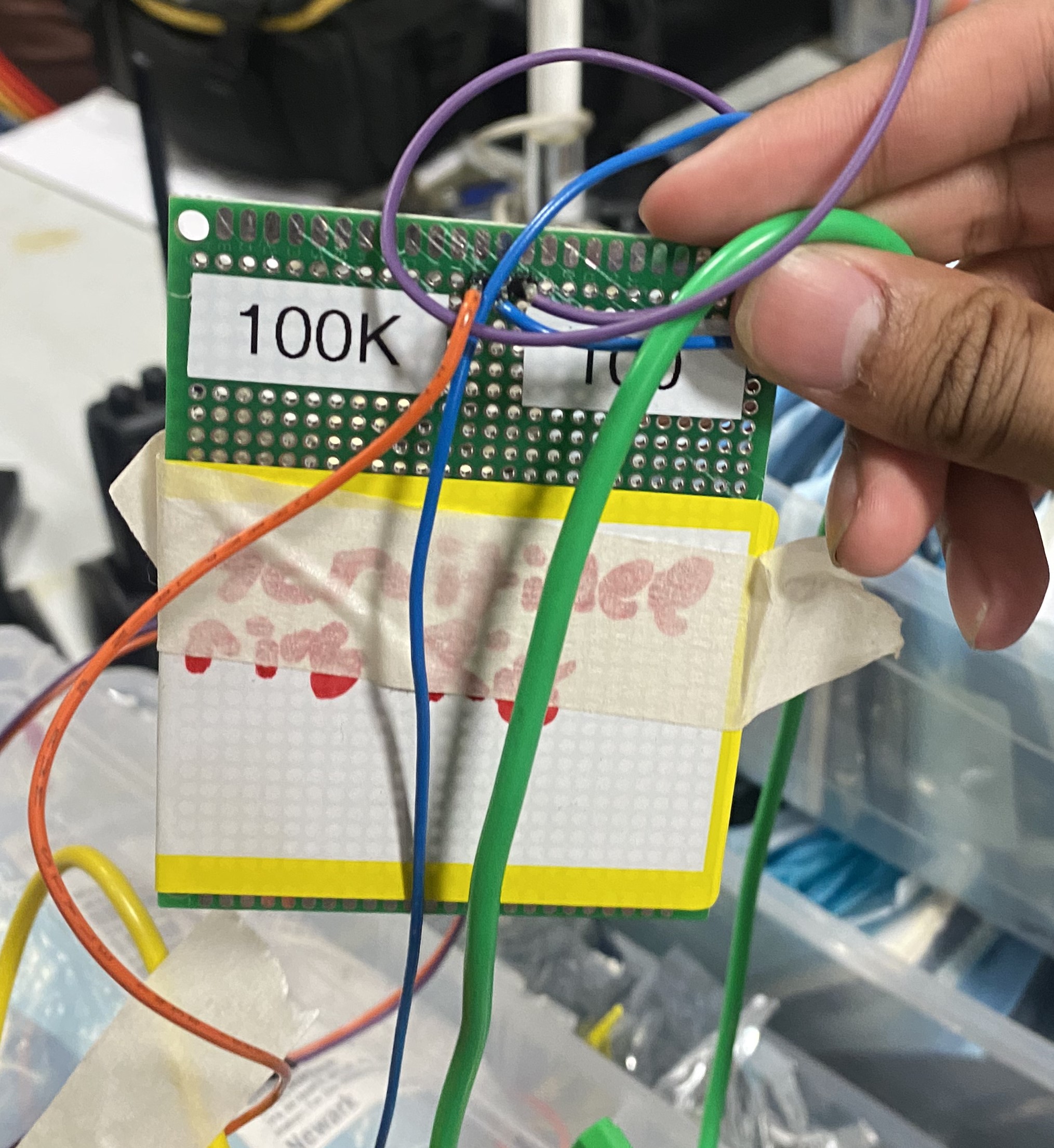
Expanded Image
Waterloo’s voltage divider perf board to simulate a shunt current sensor.
For over current scrutineering tests, they simulate the shunt current sensor by inputing a voltage into the MAX17261. They don’t actually need a current source to complete the over current test, just a voltage source.
On a perfboard they have a voltage divider that gets them to the microvolt range to simulate the shunt voltage. This is then connected to the MAX17261.
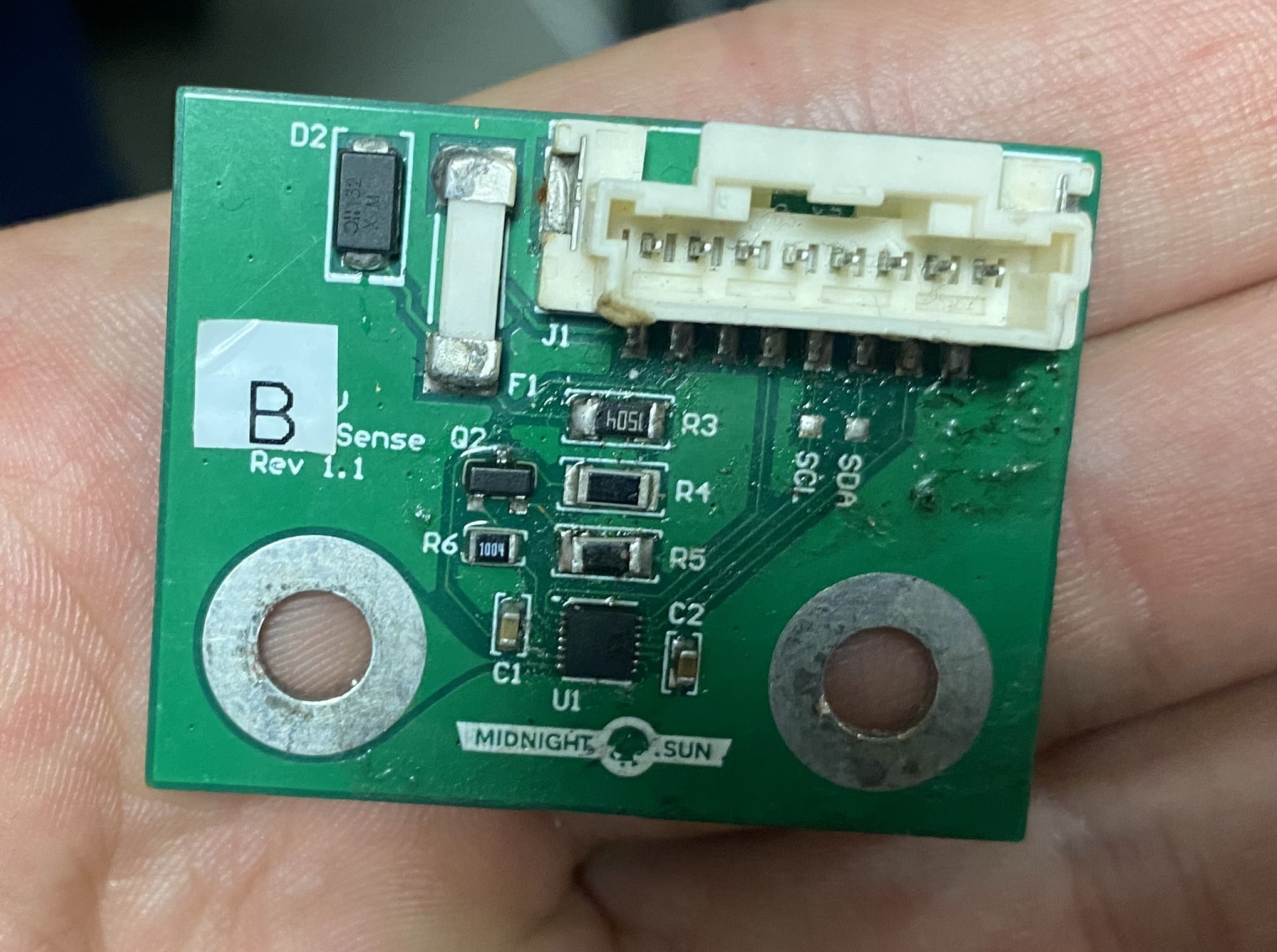
Expanded Image
Midnight Sun 15’s cell board. Note the pads for SCI and SDA, maybe they’re just filled holes for test pins.
For cell board testing, they have their own harness that gives them battery module voltages and a thermistor. This is similar to our setup but they don’t have to take out a cell board for the test and the cell boards are far more accessible.
Team Organization
I talked to Liam and Arian of the Embedded team (I think). Earlier I talked to Evan and Aiden, who are electrical leads.
Midnight Sun does not have subteams the same way we do. Instead, they have higher level teams (mech, elec, business, etc.) that all have projects groups within them. Each team has multiple leads.
This stems from the co-op schedule at Waterloo where students may often be gone for 4 months, come back for 4, then be gone again. This means you can’t have a single person owning a project, instead you need a project group where everyone is up to speed on what is going on.
Team members often jump around on different projects and get a wide view of everything that goes on in the car.
Other Points
Evan and Aiden were impressed by our simulation environment. <3 Strategy
They use Analog Front End (AFE) to refer to slaveboards and everything beneath them in the battery sensing architecture.
Midnight Sun = MS. Designing MS16 rn. Skipped MS13 because thats a gang lol.
Telemetry architecture is very similar to ours. XBee radio to laptop receiver to database (I believe InfluxDB) to Grafana. Almost exactly the same as Sunlink.
They’ve also burned through tons of LTC chips on slaveboards. Their solution to this for MS16 is to create a board that slots into the slaveboard with a bunch of headers pin on it. So instead of plugging all the headers in sequentially, do it all at once.
They use a drone camera with the 3 standard wires (red, white, yellow) as a backup camera.
7 segment display for driver. When I said this looks cool they quickly corrected me and said it was actually shitty.
Expanded Image
MS15’s Battery Pack
They have a custom built 10 Ah auxiliary battery.
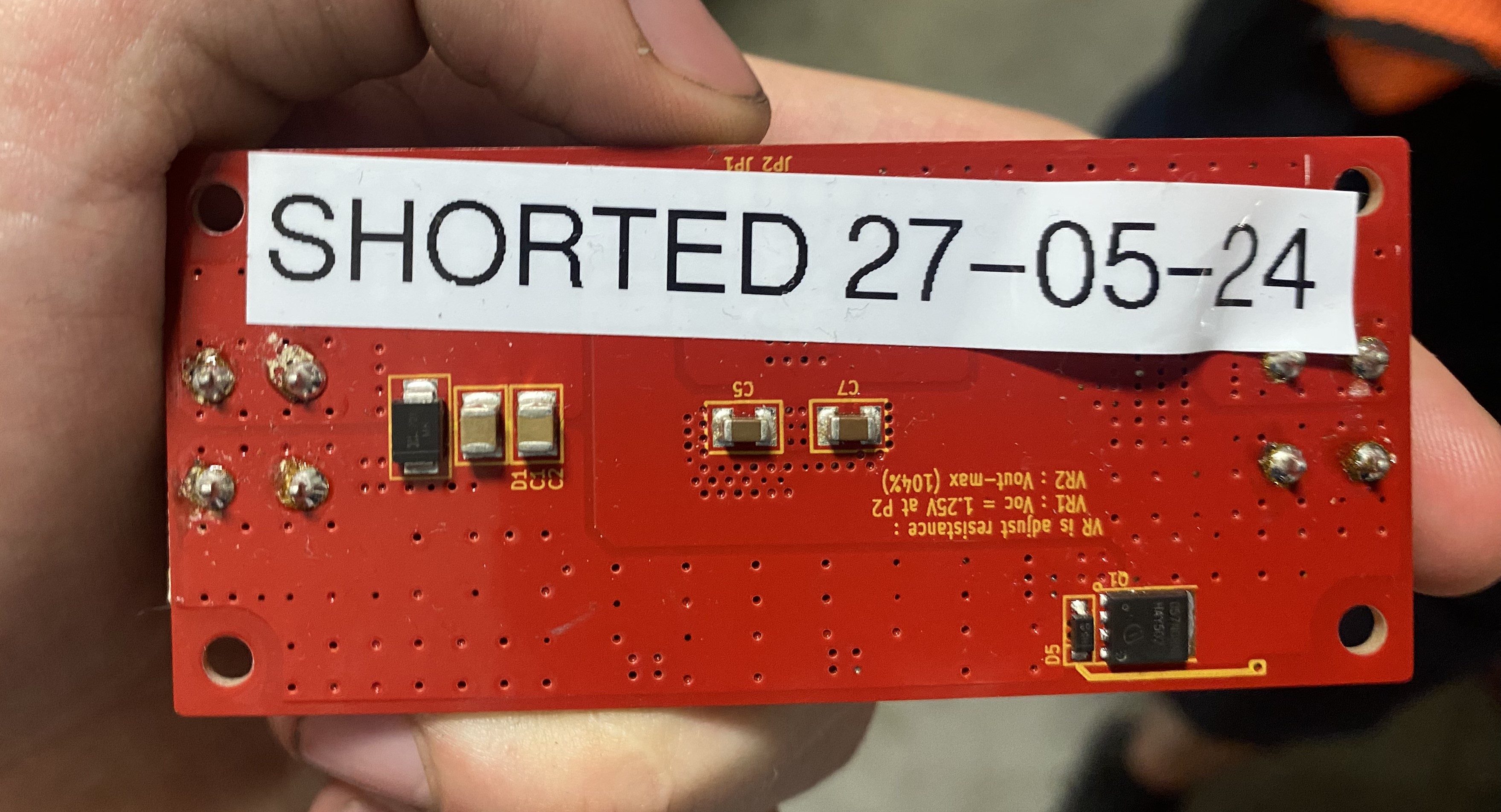
Boards that they have fried all have labels on them signifying when they broke.
What UBC Solar Should Take From Them / Ideas
Grafana Is An Industry Standard
AstroForge, the asteroid mining company that has actually launched a mission, uses Grafana for telemetry.
Zydro Marine also uses Grafana for telemetry.
Web-based telemetry also isn’t too rare. All of Starship mission control telemetry is web-based.
Andrew McCalip of Varda Space - the space pharmaceutical manufacturing company - has a public Grafana dashboard for his side project of building an autonomous boat that can sail the world. He also has a GPS dashboard to track his autonomous boat.
We should consider creating a public Grafana dashboard that anyone on the team (or alumni and friends) can access to see our telemetry. Currently, only one or two people can look at live telemetry from the car at any given time. A public Grafana dashboard - or one that Solar Members can log into - would allow anyone to see the telemetry in real time.
When I was timing up at HQ during the race I had no idea what was going on with the car and had to switch radio channels between the driver channel and the timing channel to figure out what was going on. A Grafana dashboard that any member can access solves this.
Also, we should create a GPS dashboard on Grafana to know where the car is.
Rename MDU/MDI to MCI
We call our motor interface board the Motor Drive Unit or Motor Drive Interface depending on who you ask.
To simplify naming (and remove the word “Drive”, since it’s redundant), we should rename the MDU/MDI to the Motor Controller Interface (MCI) and follow Waterloo’s naming scheme for this board.
Working Between Subteams
A great strength of Waterloo’s team structure is that members can move to different projects and work on what is most interesting to them, while getting a feel for all the different work that goes into the car.
We don’t need to adopt their entire team structure and eliminate all of our subteams, but we should encourage more cross-subteam work so everyone can get a feel for all parts of the car and discover what work they like most.
Currently, the system for allocating a member to a particular subteam is the lead deciding where a new member should be placed. Instead, we can let members move more freely between subteams and decide themselves.
Power Distribution Board
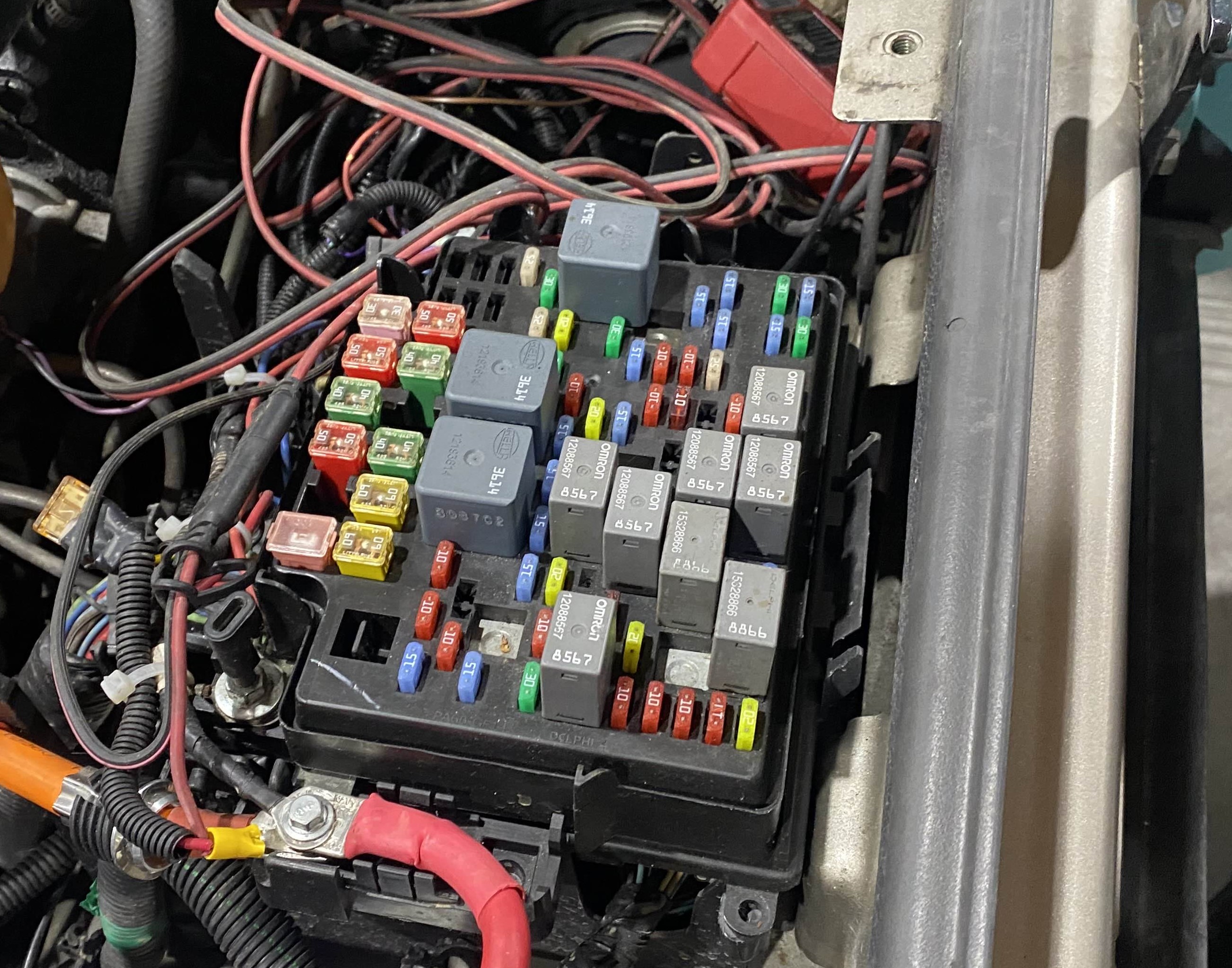
Expanded Image
Blue Force’s fuse box, fairly standard in the automotive sector.
Waterloo’s Power Distribution Board looks a lot cleaner than our distribution board. We should take more inspiration from industry power distribution boards for our next generation design. For example, we can consult autmotive fuse boards and put all connectors on the outer edge of the board.
Bootloaders
Currently an issue for us is flashing the BMS / ECU is difficult and requires opening the pack. Having a bootloader that allows us to flash over CAN or another bus would obfuscate this issue. Important consideration for v4, I believe we’re going towards JTAG for this.
CAN Splitters
Waterloo does have any CAN splitters because boards are daisy chained. This is not the industry standard and our current architecture is more professional.
However, only one other team (Calgary) has CAN splitter boards. They have them for the same reason we do, our connectors don’t have a standard off the shelf 3-way splitter. All other teams have an off-the-shelf 3-way splitter.
We should reconsider our CAN connector and the form factor of our CAN splitter by looking at what the automotive industry uses.
Our DB-9 and 4 port CAN splitter is a reasonable solution to this problem, but could be made better through a smaller form factor. Furthermore, a cleaner and more accessible wiring diagram for the car would help with understanding what all the wires in the car do.
Shunt Current Sensor
The big advantage of Waterloo’s shunt current sensor system is that the MAX17261 IC gives them a higher precision voltage reading than we get from our STM32, leading to a more precise current value.
We can consider a shunt current sensor for v4. We could also achieve a higher precision current reading by using a high precision ADC IC on our ECU, eg. the ADS1115 which I’m using in one of my projects.
For simulating an over current fault in the future it seems we could inject a voltage into the current sense line on the ECU and forego the need for a separate current sensor with 30 loops around it. Send an email to scrutineers before baselining this architecture though.
Purdue
Highlevel Overview
- Orion V2 BMS
- 36s8p Cell Configuration
- 8 Battery Thermistors Total
- 21700 50E Samsung Cells
- TE V23720-A0002-A001 battery contactors
- Mitsuba Motor
- Tritium Motor Controller (WaveScrulptor 22)
- Kevlar Battery Enclosure
- Power Prioritizer in place of relays for supp/dcdc switching
- Raspberry Pi for telemetry
- 5 Spare Supplemental Batteries
- Car cost $400k, $330k sponsored
General Notes
Orion V2 BMS
Purdue uses an Orion V2 BMS, commercial off-the-shelf BMS.
The Orion V2 has an internal Insulation Monitoring Device (IMD).
Kevlar Honeycomb Battery Enclosure
Apparently, Purdue has one of the best materials science departments in the world.
Their solar car team uses a kevlar prepreg battery enclosure since it doesn’t splinter during a collision like other composites (eg. carbon fiber).
In-house Solar Cell Encapsulation
Purdue encapsulates their own solar cells in-house, using a large furnace (kiln?) that is available on campus. Again, cracked materials science department.
At ASC 2024 they claimed a dog jumped onto the solar cells during a public showing of the solar cars. None of the cells were damaged due to the strength of the encapsulation.
Battery Modules
Purdue has “sandwich” style battery modules. Notice there are two electrical modules (8x2 cells) in a single structural module.
First, polycarbonate is CNC’d to the shape of the module. Then, nickel sheets are laser cut and spot welded onto the cells. Finally, 3D printed clips hold the module in place in the battery.
They said that the cells themselves take force in the verical axis, so this is a structural battery design. Looking at the rest of the pack though, it looks like having a structural module does not reduce the structural components or mass of the pack.
Capacity Cell Characterization
They did capacity cell characterization (As opposed to impedance characterization like we did on v3) using a Kunkin load (“piece of shit load don’t even write that down”).
They take voltage and resistance measurements versus time. Samples several seconds apart for the duration of a test.
The Kunkin load ran current through one cell at a time.
They did a sweep of characterization tests on 3-5 of the cells at 2C, 1C, 0.5C, 0.2C.
The 2C test was half an hour, so the 0.2C test would be 10x longer at 300 minutes.
They didn’t spend the time to characterize all of their cells as they saw that they were similar enough from the manufacturer that they could be put into modules without much trepidation.
So, If you have a good enough cell manufacturer, it isn’t a strict requirement to characterize all of your cells.
They use 21700 50E Samsung cells and said that the trailing 0 may mean it’s a cylindrical cell (Not prismatic or pouch cells).
Some context:
The XXYY cell dimension standard gives diameter in millimeters for 2 digits, then height in millimeters for 2 digits.
A cell size like 18650 suggests the cell is 18mm in diameter and 0.65m in height.
Now I know the trailing zero means it’s cylindrical! However, this is also seems like redundant information as XXYY cells are cylindrical by default, the XX is diameter!
Operations Team
The Purdue Operations subteam has two primary functions:
- A business/marketing group focusing on social media, keeping in touch with sponsors, and general business/comp preperation tasks.
- All the leads of other subteams serve on the operations team to secure sponsorships with companies pertinent to their subteam.
This structure makes it clear that team leads are responsible for securing sponsorships for components/services they need for their subteam. Purdue’s entire car cost ~$400k, with ~$330k sponsored. >80% of the car cost was sponsored, so the benefits of having team leads explicitly responsible for securing sponsorships as part of an operations team is clear.
Leads know the exact technical requirements of needs of their subteam, so they can better communicate with sponsors. It turned out that in Purdue’s case, the vast majority of individuals on their operations team also do technical work.
A lot of the other work of the operations team is maintaining relationships with sponsors, sending resumes, calls, visiting sponsors, and sending packages with merch.
Purdue has an operations team which consists of a subteam of business/marketing people and almost every lead. The subteams in the business team work on marketing/general business/comp organization tasks. Meanwhile, the leads which are a part of the operations team work to secure sponsorships and the subteam does marketting.
Other Points
They are alcoholics (raging)
(They told me this themselves!)
(Literally me)
I was told that WSC teams start with a cooled pack at the beginning of the day. They choose cells with chemstry’s such that they have high thermal capacity and low internal resistance.
Like Waterloo, they use a Power Prioritizer IC to switch between the supplemental battery and the DCDC. Eg. LTC4418.
Purdue tried making their own DCDC, but couldn’t find a suitable transformer.
On the night July 4th one of the Purdue guys told me they did CFD on their steering wheel. Surely he meant FEA right! right? Guys the steering wheel has to be aerodynamic we should be taking notes!
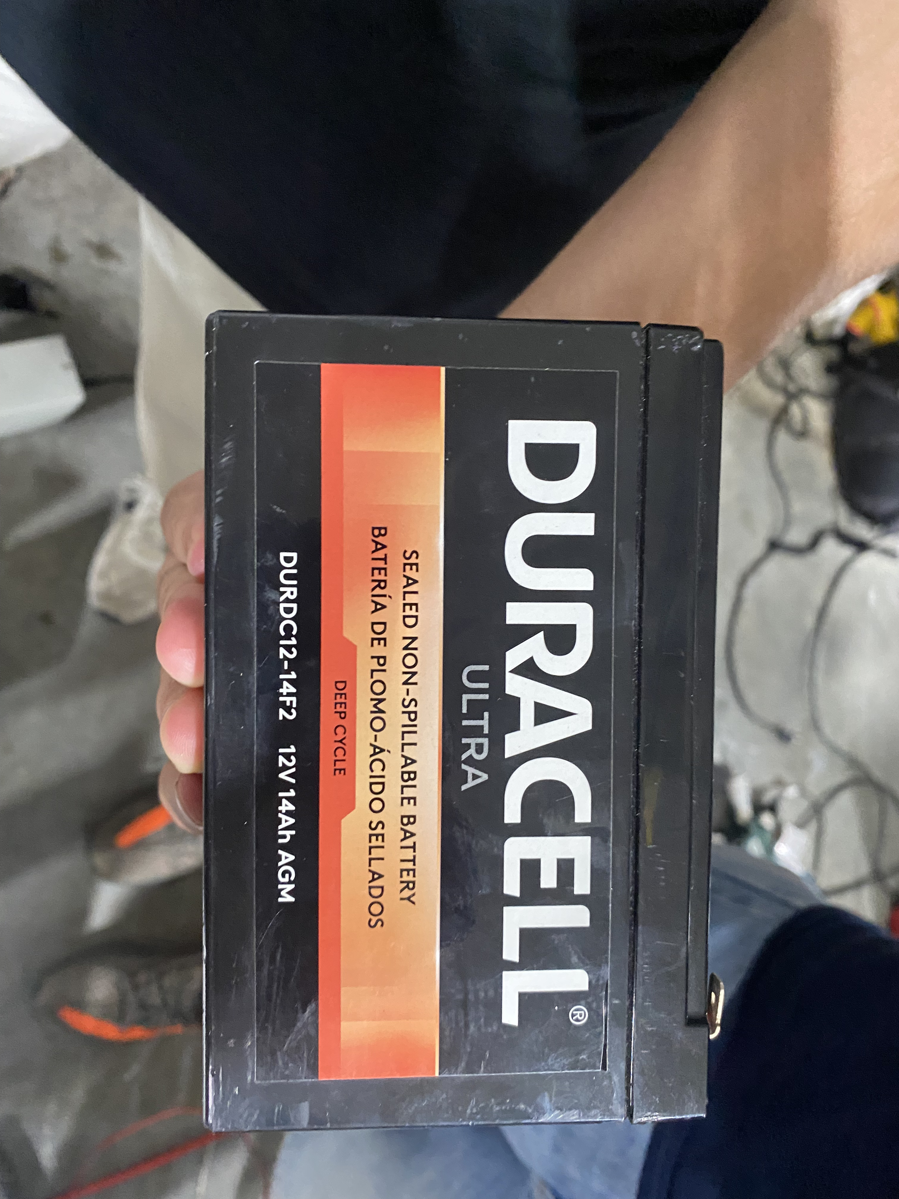
Purdue has ~5 spare supplemental batteries that the drive can swap in during racing (with the car off obv). Like us, they had supplemental battery issues and decided to solve it by having 5 spares.
Like almost everyone else, they use “auxiliary” instead of “supplemental” to refer to their secondary NiMH batteries. Regulations use “supplemental” so it’s not clear why there’s such a discrepancy.
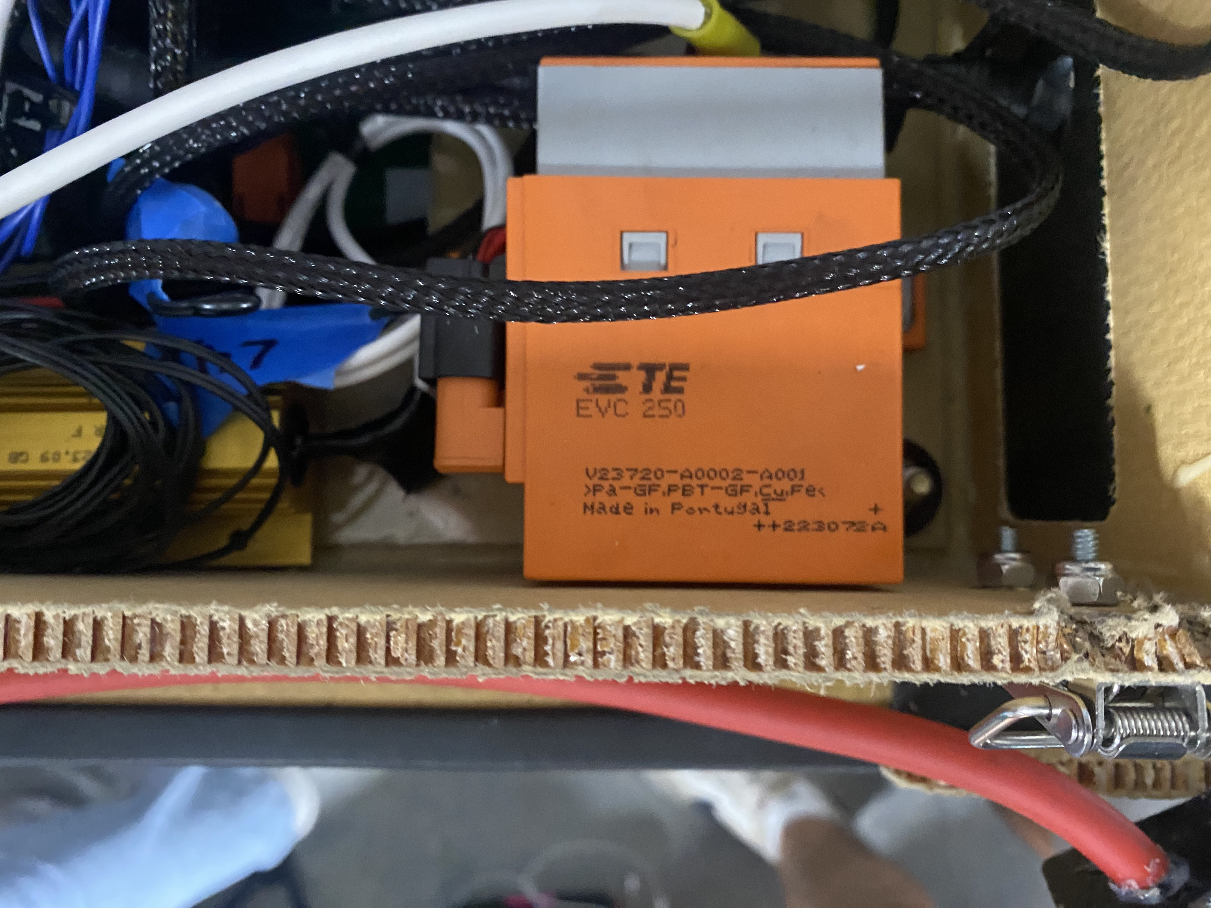
They use TE V23720-A0002-A001 contactors. 12V, IP54, 250 A / 500 V max.
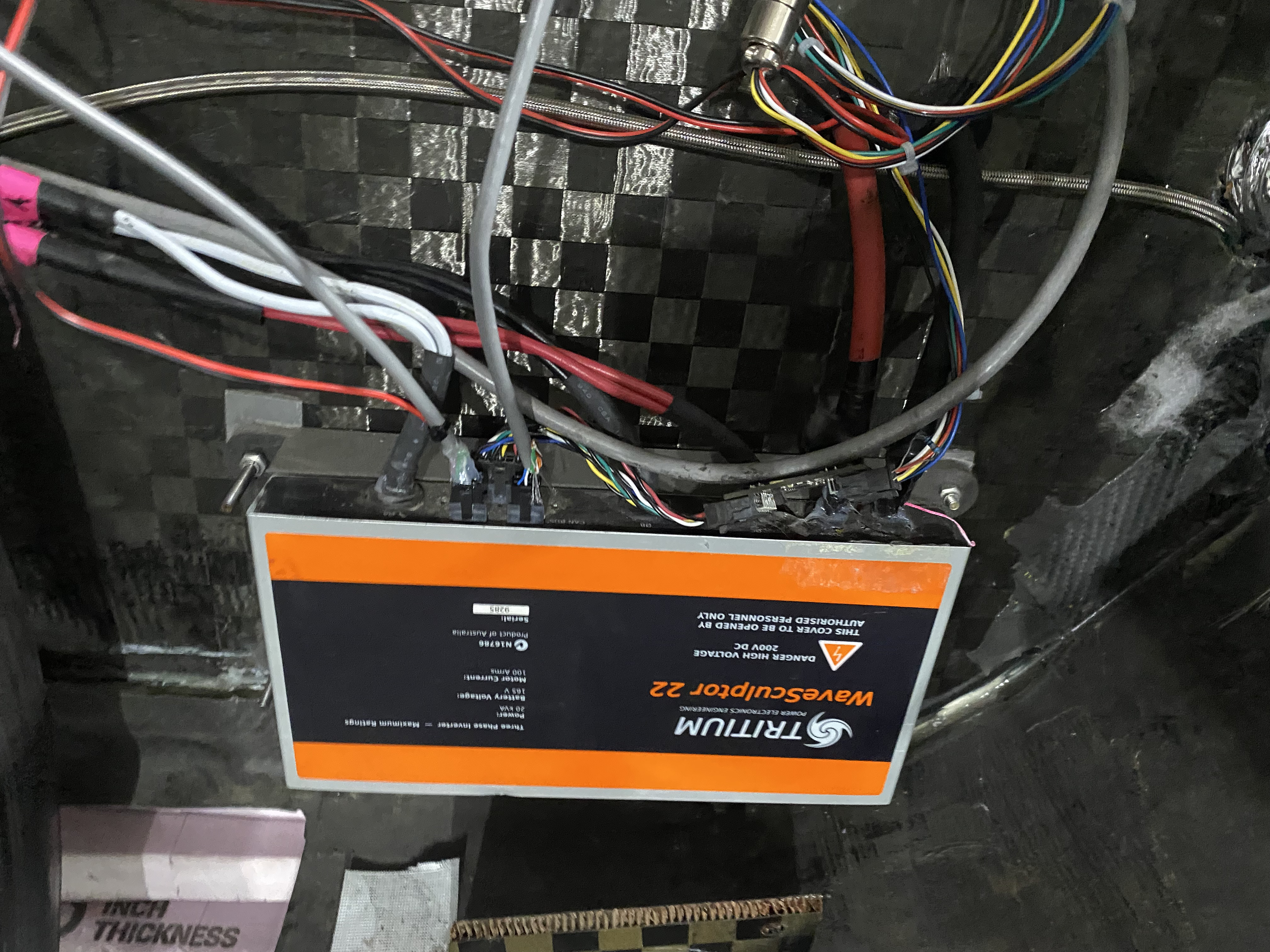
Tritium WaveSculptor 22 motor controller. WaveSculptor’s are actually quite common at FSGP.
Everytime I stopped by Purdue’s bay they were very professional and seemed to have everything in order. They made it most of the way through ASC 2024 and I expected them to do very well at FSGP 2025. However, it was only around the final day that I realized they’ve actually been having issues the entire time and hadn’t gotten on the track. Terrible failure but chill guys though! Especially on the 4th of July!
What UBC Solar Should Take From Them / Ideas
They are alcoholics (raging)
Operations Team
UBC Solar should consider having a structure similar to Purdue’s Operations team, where aside from marketing and business tasks, all team leads are involved in securing sponsorships for their subteam’s needs and other general operations tasks. This makes make it explicitly clear that leads are responsible for securing sponsorships of components/services/money and that they are involved in the financial operations of the team.
Power Prioritizer Instead Of ECU Relays
Our current ECU uses a relay to toggle between the supplemental battery and the DCDC, and a 1uF capacitor is required to smooth the transition. We should consider using a Power Prioritizer on the next ECU (Also, rename Elithion Control Unit to something move professional like Power Controller Unit).
Illinois (One of them, probably Illini)
I spoke to someone with the Illinois team for a couple of minutes and a point they attempted to ingrain in my mind was that you must make sure that your high wattage crimps are good.
They had an issue that rattling crimps in their Anderson connectors lead to quickly varying contact resistance, heat buildup, and melting of the Anderson connector.
Puerto Rico
TODO: Make notes look nicer
Race capture 4 used for driver sensing. It has a can I put from their orion
Raspberry pi powers disappear.
Two driver fans
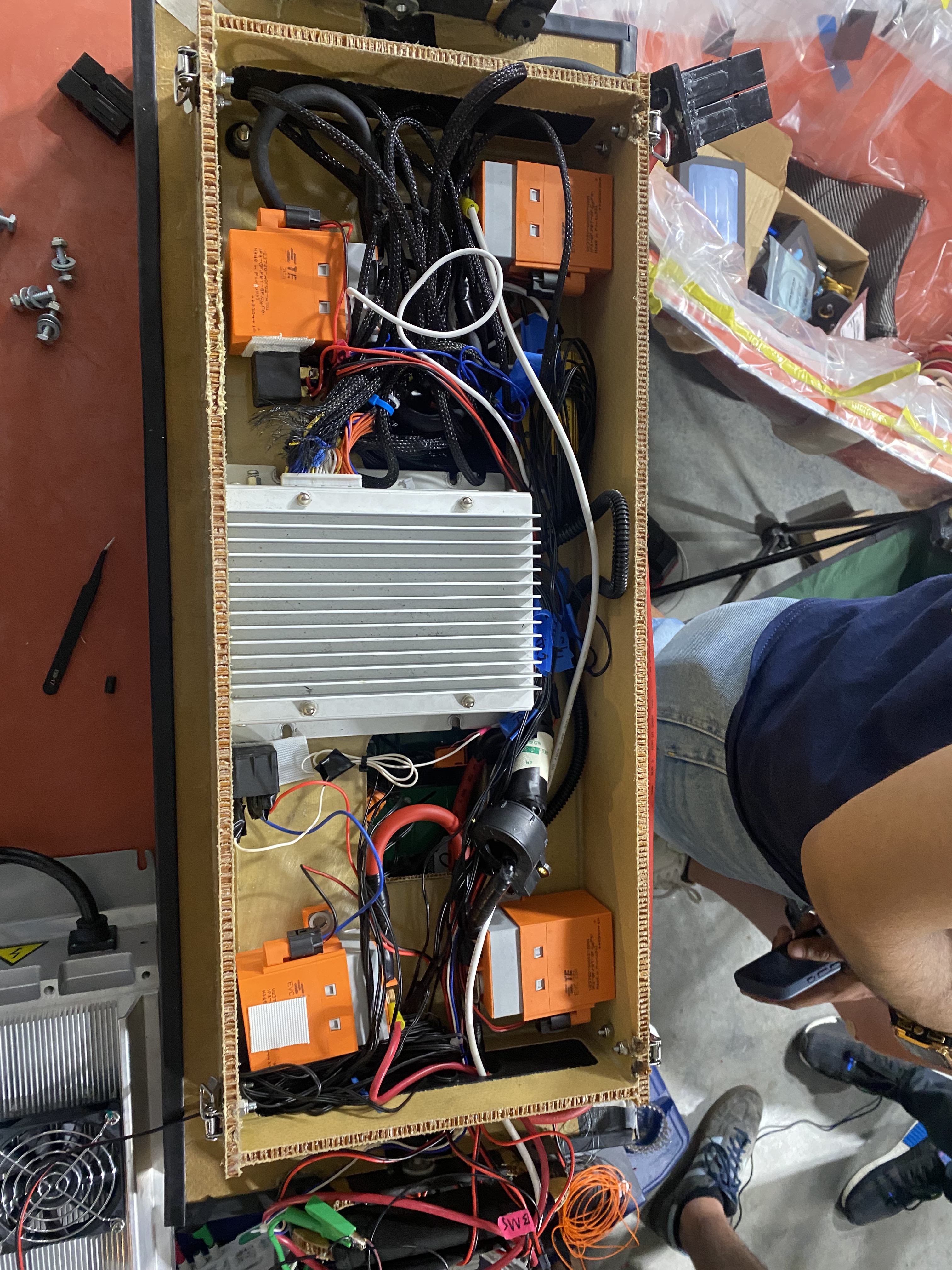
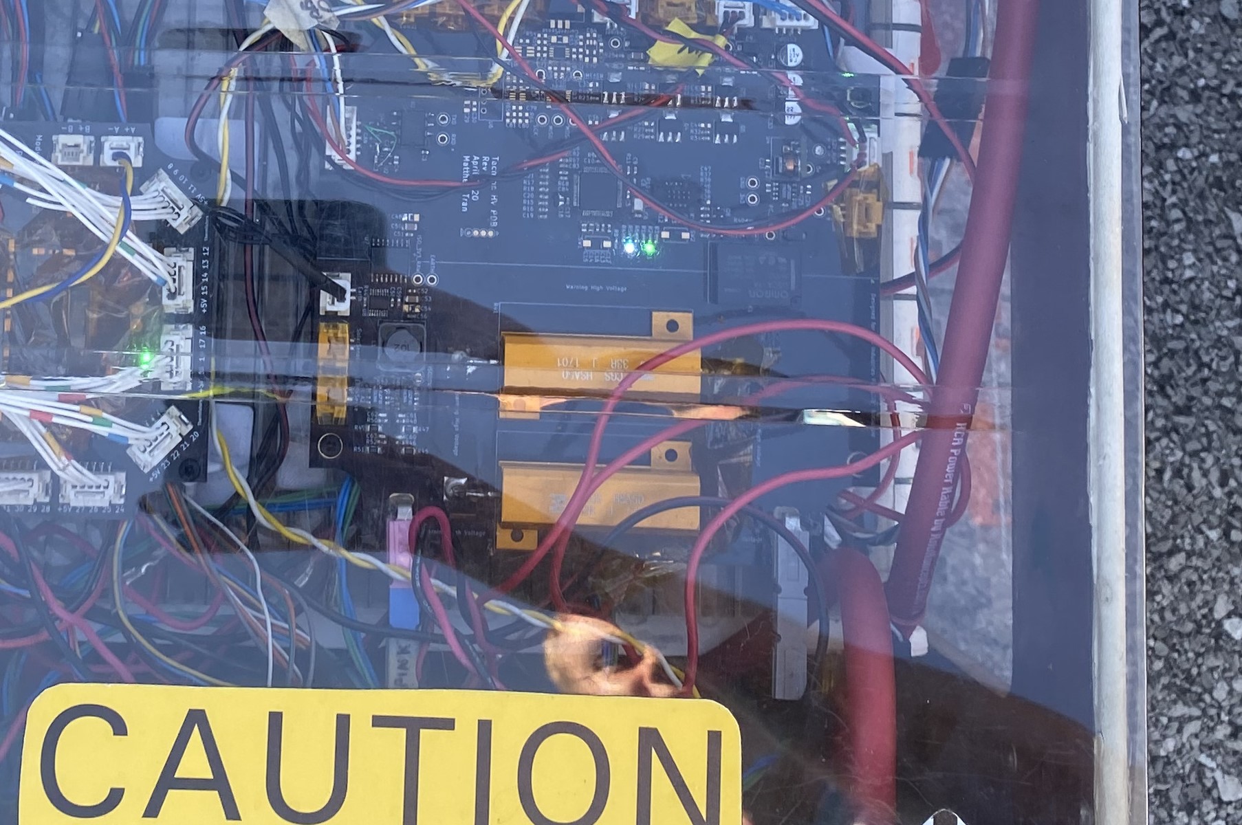
Space limited in pack due to cage (other team?) so power dist is external. High voltage inside a glass cage for motor, arrays, battery, probably DCDC.
No can to raspberry, they do it through the race capture Quateo.
Bars between contractors, everything else wires. Bars because better and no bars anywhere else because hard.
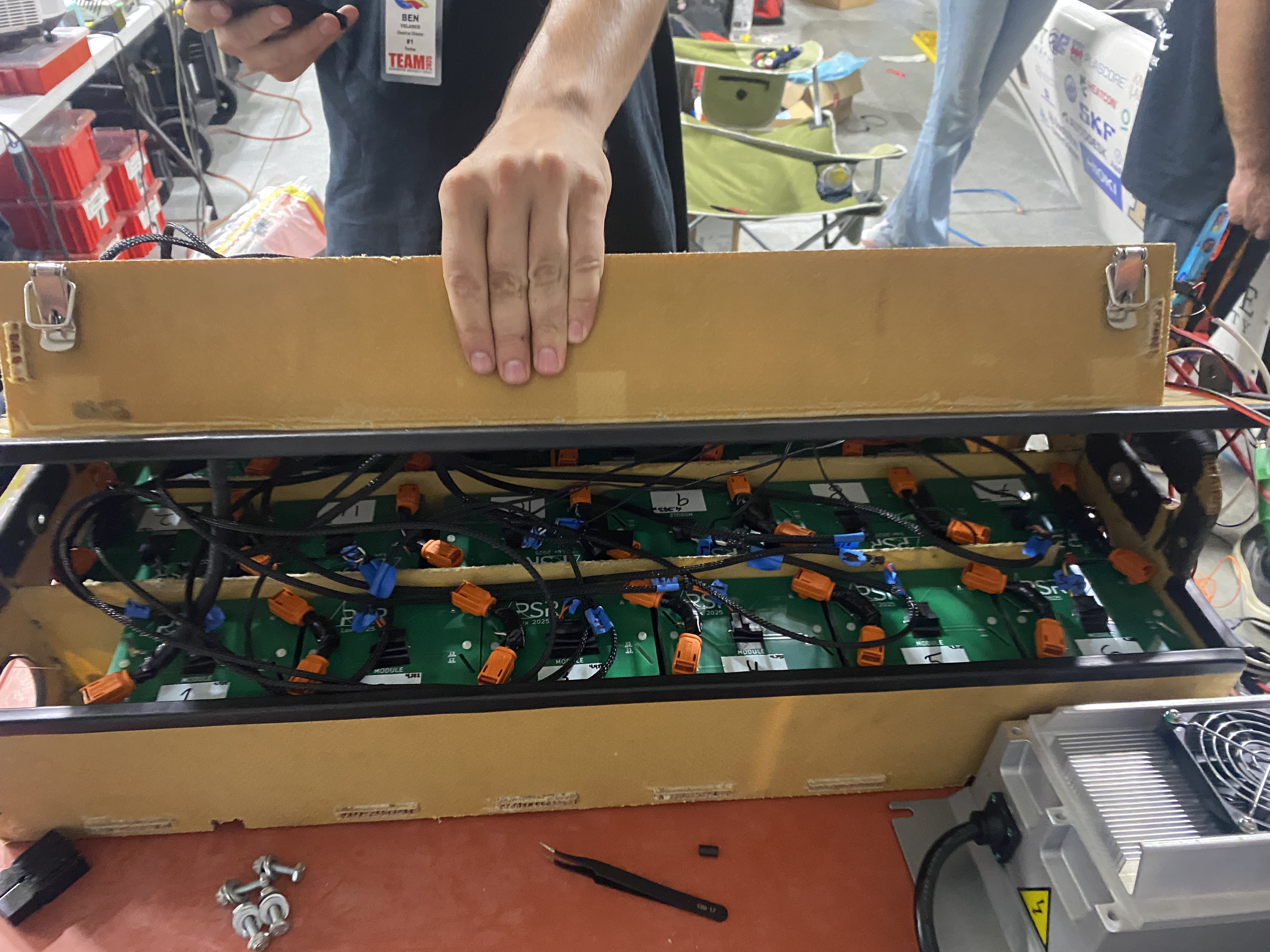
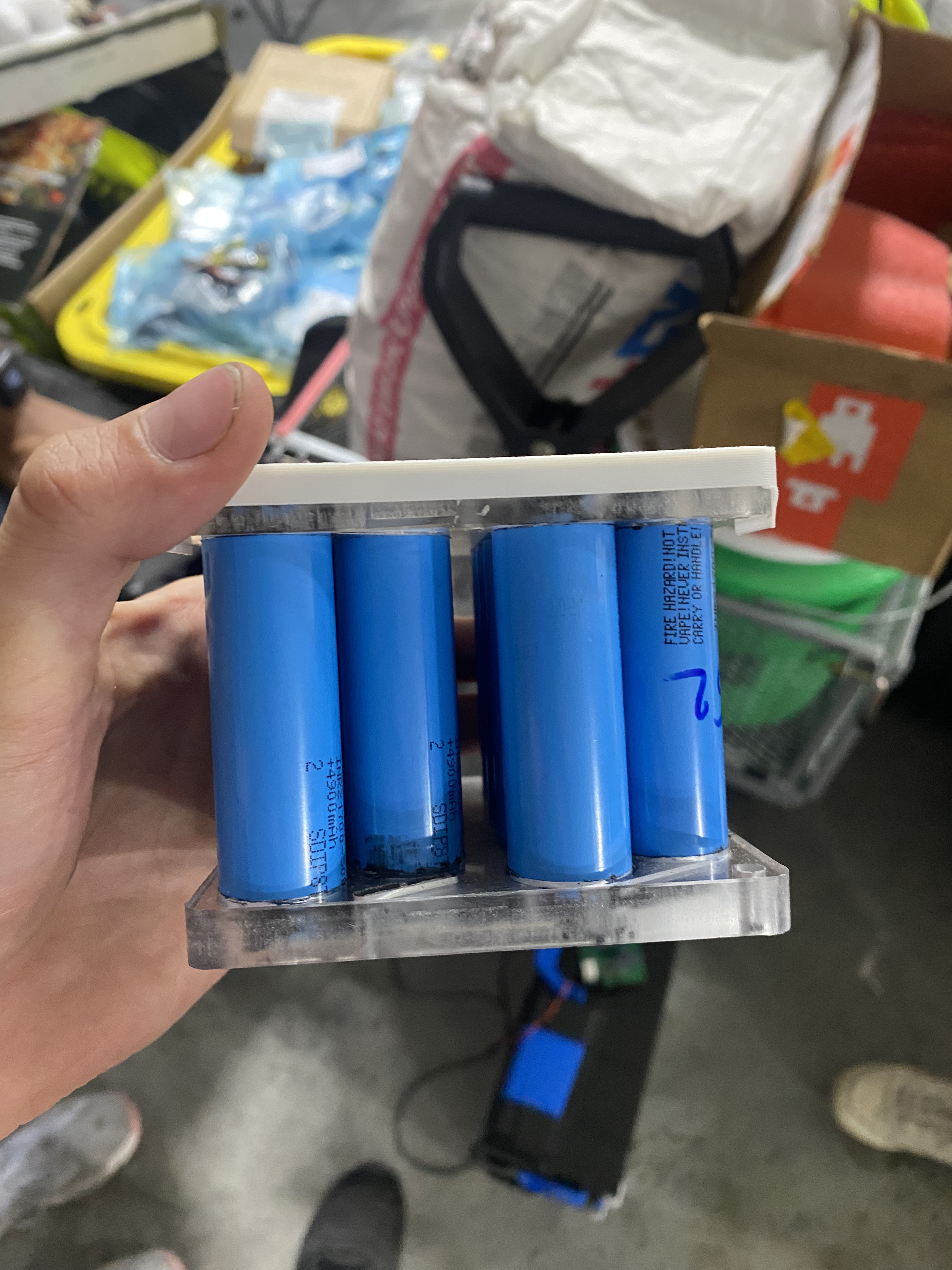
Two big bars of cells. 7 high, dozens long. 30s14p. See the image.
GPS map of track with the race capture, track position, very cool.
Didn’t ask about telemetry! They looked bare bones though maybe don’t have it or CAN logging.
Playing music on drums (handheld)!!!!
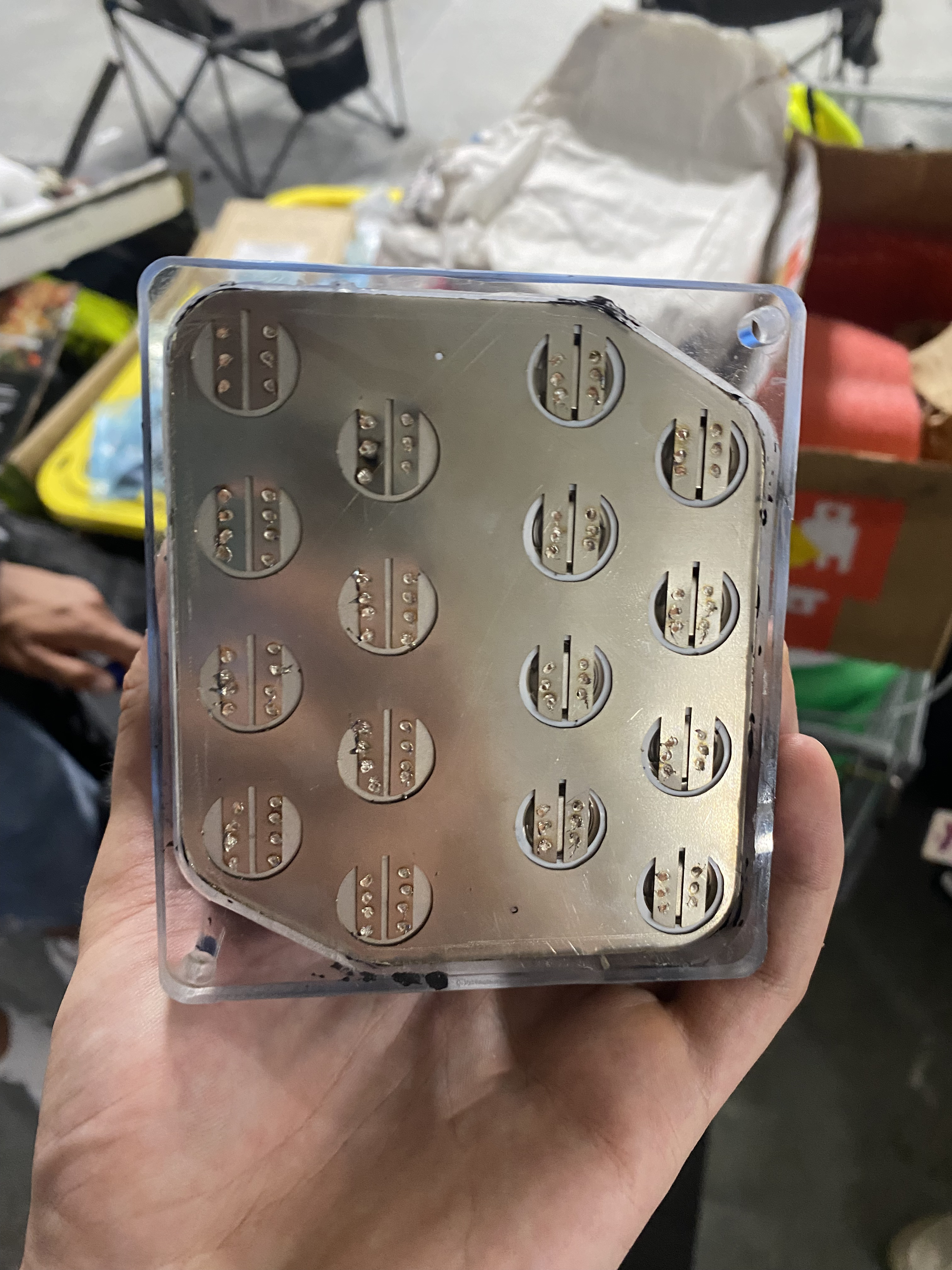
Have to take off all nickel tabs to get to a cell in the middle of a bar.
Copper bus bars.
LCD driver display I think high res, well if it shows track position.
Single piston thing spring on the wheel.
External DCDC you can see in the image.
Wisconsin Madison
Lights testing:
If one turn signal is on, the daytime running lights on the other side should be on.
Fully removable top shell way easier for array work.
What UBC Solar Should Take From Them / Ideas
Alternative Slave Board BMS IC
For their next gen car, Wisconsin Madison is using the ADBMS6830 IC which supports voltage sensing of up to 16 cells, isoSPI or I2C up to 2 Mbps, passive cell balancing control built-in, a 16-bit ADC, and up to 10 GPIOs pins.
From the teams that use the Orion v2 BMS, I’ve heard that they have little issue with plugging modules in the wrong order due to internal protection circuits within the Orion v2.
Berkeley
Highlevel Overview
General Notes
What UBC Solar Should Take From Them / Ideas
Module Sheet Design
TODO: Wait for Ezzat to get back to me
Precharge Resistors on PCB
On the primary board in Berkeley’s battery pack, they have an isolated high voltage section with high power resistors, presumably for pre/discharge.
This design eliminates a non-trivial amount of space in the pack since far less control board space is required to to let the operator install the bolts or wires to the resistors. Furthermore, no margins are required around the precharge resistors for installation of the bolts or wires since that work can be done outside the pack / control board. Finally, no external relays (or wires from the ECU to these relays) are required to toggle the resistors because they are integrated onto the HV side of the PCB, like our current discharge resistor relay.
Integrating HV components like pre/discharge resistors and their relays onto a PCB will allow us to save space in the pack, reduce the number of loose wires in the pack, and simplify the control boards overall design.
Self-Encalsulation of Solar Cells
Berkeley told me that majority of the teams at FSGP encapsulate their solar cells in-house. The ones that don’t (like Berkeley, AppState, us) have issues with damanged cells.
Purdue’s experience with self-encapsulation is that it was strong enough for a random dog to jump on the top shell without any physical damage or degradation of the cells.
For v4, we should consider the path of self-encapsulation of our solar cells for greater durability, albeit at the expense of higher mass and a non-trivial amount of member time.
MORE NOTES
Majority do self encapsulation.
Gochermann encapsules theirs.
Theirs is (n’t???) self and easy to damage.
- Module Sheet Design
- Precharge resistor on the PCB, makes integration simpler but HV on PCB, not too hard
- Each module has 5 thermistors along its line
- Majority do self encapsulation.
Gochermann encapsules theirs.
Theirs is self and easy to damage.
Michigan has active wheel farings with a spring so faring goes out on turns, they might have in older car, might next car. Currently magnets, bolts on top, magnets bottom and tape.
Battery and solar is at charging area, mech fixes so rest of car is here!!
Now at charging area for elec guys:
12p34s
In house interconnects between modules
Modules have cells vertically, they swap direction each time so interconnects are only on one side.
Module logics, LTC something.
High voltage power distribution board. Pre charge on it!!
BMS board.
Two victor DCdc, heat sinks.
Each module has 5 thermistors, white wires.
Miles connector soldered onto module board.
MPPTs: bankrupt, 13 years, and for next Feb, Dilithium power company, photon 3.
Homemade kinda spare mppt.
Can connector: phoenix conmector
M8 5 pin
It’s just a wire going into everywhere, why do we have can splitters?!?!?!!?!!!
Molocell, Taiwan, Canadian factory, M35A. “They’re great cells highly recommend.”
Omg this battery
E stop on battery
Motor controller Mitsuba
Gochermann solar panels
Maxion gen 3 solar cells
Motor: Mitsuba too
No cfd for battery, just cell
Hand calcs for fans
Literally in notebooks for five hours and a text book. Fluid dynamics test book, heat transfer. Model convective gets transfer over rows of cylindrical banks is the name of the chapter.
24 milliohns per cell. Used for be 36 for their last gen. He says Deev says we’re around 40.
3.6 kW absolute for two motors.
Modelled for dropping cells 5 degrees below steady state battery temp in the model.
Do you want three slow fans or one fast one??
M1096 D3 motor
3.6 kW is max regen
5.4 kW is max power into motors
Better numbers
Majority do self encapsulation.
Gochermann encapsules theirs.
Theirs is self and easy to damage.
Top wrap sponsored Esteban’s wrap
ETS
What UBC Solar Should Take From Them / Ideas
700km Of Track Testing, Mostly in Rain
ETS did 700 km of track testing before FSGP/ASC 2024. They did this on a 7km track near their campus (PMG Technologies Test and Research Center) and most of their testing was done in the rain.
If UBC Solar did more long-duration track testing we would have found issues like the motor power wire colliding with the motor rotor and melting, the break caliper falling out of its housing and getting stuck (effectively always breaking), and the MDI (Motor Drive Interface) board shorting during FSGP 2024 due to water ingress.
ETS also uses a parking lot for dynamics testing like us, but we focused solely on dynamics testing and no long-duration stress testing on a track (especially in rain, like we would likely see during ASC).
Note that ETS didn’t do wet break testing, and did hand calculations instead.
Focus More On Waterproofing
ETS plastic wraps all of their PCBs and their 3D printed enclosures. Antoine Lapointe, technical direction of ETS, told me they “Wrap the shit out of PCBs.”
If we can’t prevent water ingress through the aeroshell (this is effectively what industry does, good exterior seals), then we should do everything we can to prevent water ingress into PCBs and their enclosures.
This can be acomplished through fewer holes in enclosures, tighter tolerances around connectors, and plastic wrapping the shit out of our PCBs. Connectors could still poke out of the plastic wrap and we could have flashing GPIOs sticking out as well, as long as nothing on the PCB is shorted.
Carbon Fibre Mount for Horn
To prevent future issues with our horn being too quiet, we could mount the horn on either strong bands (eg. like the seat belt), or on a carbon fiber mount. This way less kinetic energy is being transfered into the body of the car and more of it emerges as kinetic energy in the air.
ETS mounts their horn on a carbon fiber mount that is not placed on the center line of the car. Lapointe told me: “I don’t know why you decided to put it in the middle, it doesnt change much.” He proceeded to say that mounting is slightly more difficult and the acoustic profile of the horn doesn’t change much.
“Keep the Wikipedia in shape”
ETS members write a wiki page for every project after it has been completed. This way insights made along the way, an SOP, or ideas for a next generation design are all documented in a single accessible place. On UBC Solar an issue that I run into is not being able to easily find information on past projects which are hidden deep in Monday or in a design review document deep in Google Drive. Having a wiki page for every project and relevant links to design reviews, SOPs, Monday updates, etc. would make it much easier to find information on past projects.
ETS also has a centralized reflection on their wiki after every competition. UBC Solar currently has around 6 reflection documents (including blog posts that are otherwise not easily accessible to future members) for FSGP 2025 and no centralized place to find them. These documents should all be linked on a single wiki page for easy access.
We also have no centralized place to find all previous competition images and we found FSGP 2024 pictures after one member seemingly randomly stumbled upon them in a Microsoft Sharepoint folder. This would also be useful to include in a centralized competition reflection wiki page.
More fun (and insightful) Antoine Lapointe quotes:
(Imagine these in a Quebec accent for maximum effect)
“How do you make sure your team knows how to build a good car for the next generation?”
”Take notes. Take notes.”
“Keep the Wikipedia in shape.”
“You guys have a lot of wires. Less Cables.”
“It would have been pretty easy for us to win here … with six square meters of cells.”
MORE NOTES
Prohelion BMS off the shelf
They test PCBs extensively before putting it in the car.
Marand motor, pretty old
Tritium, wavesculpter 22
Elmars MPPTs
Cell: 2170s, Mun Mull? Cells.
Good manufacturer so all the same internal resistance so no big characterisation
Encapsulation is Suncat Solar
Every project has a page, wiki.
Info on every comp, the dos and donts
WSC is way bigger and you try to keep stuff secret, no public wiki
17 of their people going to WSC.
40 teams ish at WSC. Mostly SOV.
Wiki is done after the project, some pictures, what needs to be upgraded.
Sometimes do design reviews. Mostly based on if people are confident in what their doing.
What is a monocoque.
Bullets are more aerodynamic but less stable.
Manufacturing is easier for bullet.
Antoine Lapointe.
Mostly undergrads
Observer here, car is being shipped To WSC. He’s
“It would have been pretty easy for us to win here … with six square meters of cells.”
They were at 80% SOC last year after FSGP, not pushing it, keep it ready for ASC.
Do as much testing as you can, so you come here with a car that works.
They have a 7km track, where they test. Dynamics in parking lot.
They don’t do wet break testing, calcs instead.
Driving a few months before for testing. Sometimes delays.
This year 700km of tracking testing before comp. Most of it was in rain too.
Everywhere cerane wrap.
“We wrap the shit out of PCBs.”
Wrap the boxes around PCBs.
3D printed PCB enclosures.
They try to just have CAN wires everywhere. He doesn’t know how they do power.
Lights have two molex to each light. Light controller PCB.
“You guys have a lot of wires.”
Each board has Can in and out.
“Less cables.”
“You guys have a lot of cables.”
They have a dashboard completely on the wheel, just can coming out of it.
PNG technology is the track.
CNC aluminium roll cage. brian scrutineer doesn’t like it.
Most Machining done in house. 5 axis parts not in house. Like roll cage, too big for CNC.
Carbon fibre wheels brought from GH Craft.
“They are popular carbon fibre wheels for solar cars, only solar cars.”
CAN connector: M12 or M16, “the msot reliable connector you know.”
“I know screw on connectors are fine.”
Carbon fibre mount for horn to aero shell.
Can put horn in the side, “I don’t know why you decided to put it in the middle, it doesnt change much.”
Easier to mount o m the side.
Ease of manufacturing is why they go bullet, “for us it’s more aero.”
6 square meter on the new bullet.
About half the size of the space were in right now at comp.
Two zones for wet layup and pairing.
They also have a specific building for design teams.
More and more design teams at ETS by the year.
Teams that don’t need garages just have a room.
“How do you make sure your team knows how to build a good car for the next generation.”
”Take notes. Take notes.”
“Keep the Wikipedia in shape.”
Say what works and what doesn’t.
“We just started making good cars five years ago maybe.”
2022 didnt run at ASC, then they got 2nd place.
Grab as much knowledge as possible from previous members.
Anytime your off the track there’s. A yellow shirt with you. Observers like ASC.
At WSC observers sleep eight eg teams like food and sleep.
“You’re happy when you’re with Michigan.”
They’re camping I the desert for WSC.
Monocoque
They do plugs out sources then they do molds and parts in house.
No active wheel fairings, time constraint because of WSC rule change. 2 months earlier and bigger arrays.
Manufacturing was less than a year.
Started in September done in April.
Design was earlier.
Calgary
What UBC Solar Should Take From Them / Ideas
Cellular Telemetry
Calgary’s Solar Car team and a few other use cellular data for telemetry instead of radio. Calgary in particular uses a Raspberry Pi with a cellular modem to send telemetry data to a server hosted by one of the big providers (eg. Amazon, idk which one they use).
UBC Solar spent several months developing a cellular telemetry system for our current car, but we got hung up on the need for a static public IP address. A sim card with a static IP costs on the order of $1000. Not sure why this was an issue and none of the other teams I spoke to had any issues with a static IP.
Separate Power Lines For Critical Systems
The majority of Calgary’s boards are powered over a 12V wire in the CAN harness. They have separate power lines for critical systems like the strobe lights and BMS so they stay powered during a fault.
UBC Solar’s third generation car already has separate power lines for all boards and it would be purely a firmware change to separate critical systems from non-critical systems that don’t need power during a fault. We should consider having this separation in our next generation car. All non-critical boards could also be powered off a shared 12V in the CAN harness.
MORE NOTES
Separate regen pedal.
Raspberry pi running hdmi display and cellular modem without static ip.
Can splitters!!!!!!
St link usb c to flash.
fucking drink holders!!!
USB C CHARGER!!!
Molex microfit connector for can
JTAG is a standard connector too?
Fuse board fans, display, all lv systems. Can 12V input.
Separate critical system and CAN power lines.
Battery, Strobe light, on critical system.
No estop for driver
18 kWh
Driver control boards stacked.
Power board in the stack, it distributes power to the stack and it. Only top board in the stack has an STM32 F4 or L4. then in stack is driver input board for mostly buttons and pedals.
630-640 ish kg.
33s
Nominal voltage 108.
18650s
Maran motor and motor controller
Some type of carbon fibre for the battery, different from chassis.
5 pre charge boards, one master BMS, Orion BMS, switch board for emergency switch, dcdc board with aux and high voltage, and 12v selector.
They did a lot of cell characterzi, idk of capacity or impedance.
A much of word docs for documentation.
In the middle:
- CAN
- Lights to the back
- Key signals for on
Pi and modem have static local ips.
McMaster
McMaster uses sigma clad for module sandwiches contacts. Sponsored for free. before they had a design with tons of spot welds and bus bars, then talked to a power electronics professor.
Hexagonal pattern of cells horizontal to air flow.
RJ 44 for can and Can debug blue (blue).
12.96 kWh, used to be 18kWh it is the limit for MOV.
Off the shelf seats they can’t find receipts could have been stolen lol.