Learning About Motor FETs and Hall Effect Sensors Live at FSGP 2025
Observed Issue
At FSGP 2025 we fried our motor and replaced it with the University of Toronto’s spare motor. When we had it set up in the car and pressed the accelerator the motor would rapidly oscillate back and forth. Instead of the expected smooth rotation we got shaking where it would move a couple of degrees in one direction, then reverse a couple of degrees very rapidly, and repeat.
These two videos shows the motor oscillation.
Background On Motor FETs & Hall Sense Lines
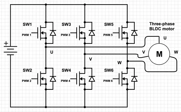
(Figure 1) This diagram shows a 6-FET motor controller, like the one we have in the car.
(Figure 2) This diagram shows how successive electromagnets are activated as north/south poles to push/pull the rotor. This is achieved through the use of the 6 motor FETs.
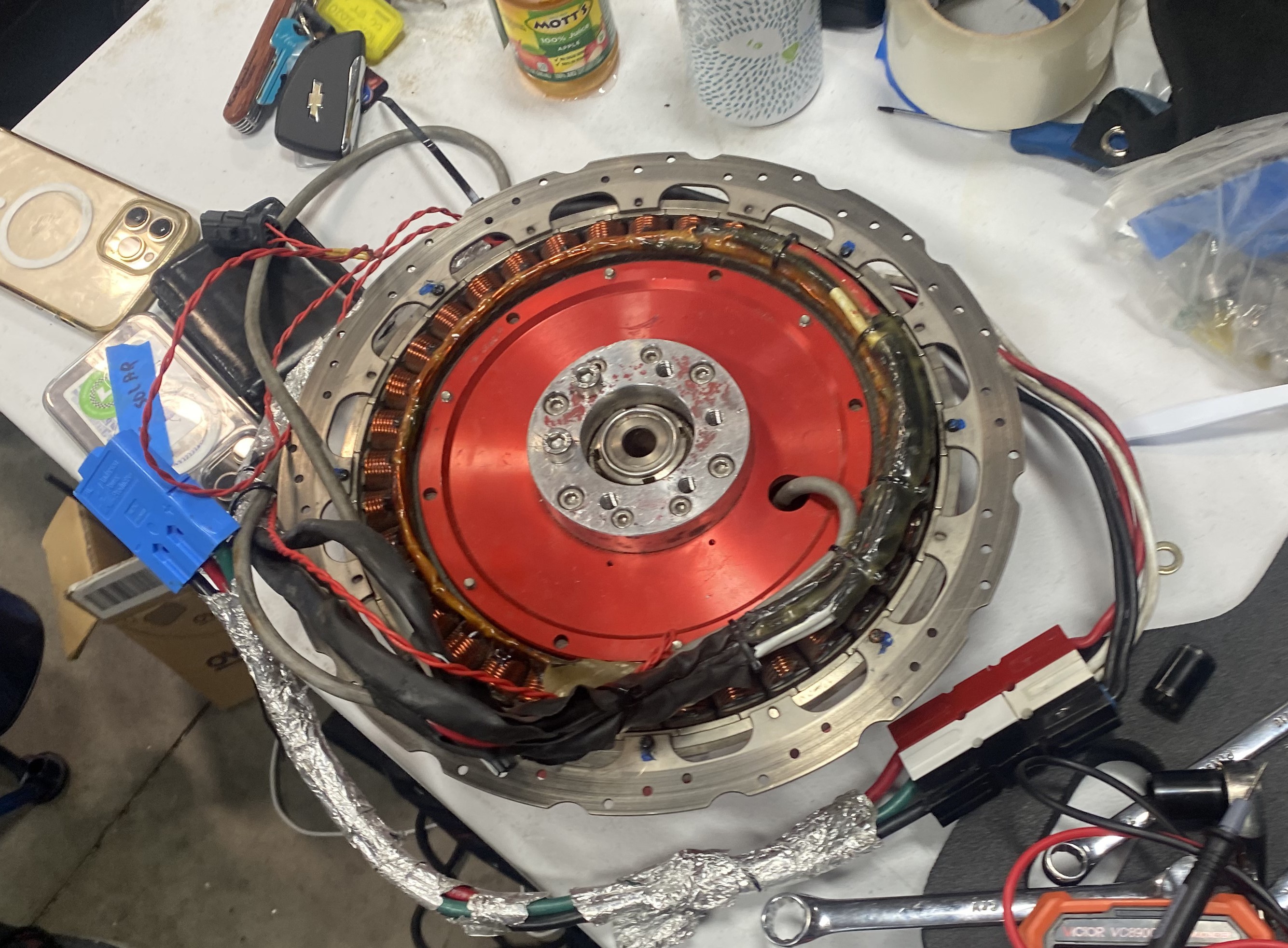
(Figure 3) Notice the copper wire coils as part of the stationary element (stator) and the metal outer rotating element (rotor). Notice that the motor power wires enter the stator.
Motor FETs
We use a Mitsuba M2096 D3 three-phase Brushless DC (BLDC) motor. A BLDC motor operates using a permanent magnet rotor and stator coils arranged in three phases (labelled U, V, W).
Each phase has two transistors (FETs) associated with one. One connects the phase to positive DC voltage, the other connects it to ground.
By toggling which phases act as north poles (positive) and which act as south poles (negative), we can control the force on the rotor’s permanent magnets. When this is perfectly timed with the movement of the rotor, with each switch we can give the rotor another kick to get it to a higher velocity. Figure 2 illustrates this. Take note of how important timing is to this system, if you don’t have the proper magnets pushing/pulling the rotor at any given time, it will not spin smoothly.
Here’s a nice Munro & Associates video on the topic of the Cybertruck Inverter that explains this in more depth with physical examples.
Hall Effect Sensors
The motor has three hall effect sensors that are spaced 120 degrees apart. These hall effect sensors output a high voltage when they have a rotor magnet near them.
Hall effect sensors output an analog signal whose amplitude varies with the strength of the magnetic field it is observing. The motor controller is a digital device so this analog signal is encoded using a comparator, which outputs a high voltage when the analog signal crosses a set magnitude.
As the motor rotates, you get a sequence of highs and lows from the three hall effect sense lines that looks like this:
001 -> 011 -> 010 -> 110 -> 100 -> 101 -> 001
Notice that in the example above we see the 1’s gradually moving left as the motor “spins.” The direction that the 1’s move tells you the direction the motor is spinning.
Eg. 101 -> 100 -> 110 -> 010 shows the motor is reversing as the 1’s are moving right, where in the previous example they were moving left.
Given the three bit digital signal from the hall effect sensors, the motor knows what state it is in and which coils to activate. As discussed previously, this is crucial to give the rotor a new “kick” at the optimal time to increase its velocity.
Saman Niksiar (elec lead) explains this concept at comp in this video.
Note that in the video the amplitudes on the oscilloscope were incorrect because we didn’t know some probes had a gain value and one of them was set to 10x. Evan Stumpges - Scrutineer, head timekeeper, and sponsor of FSGP - pointed this out to us.
Our Solution
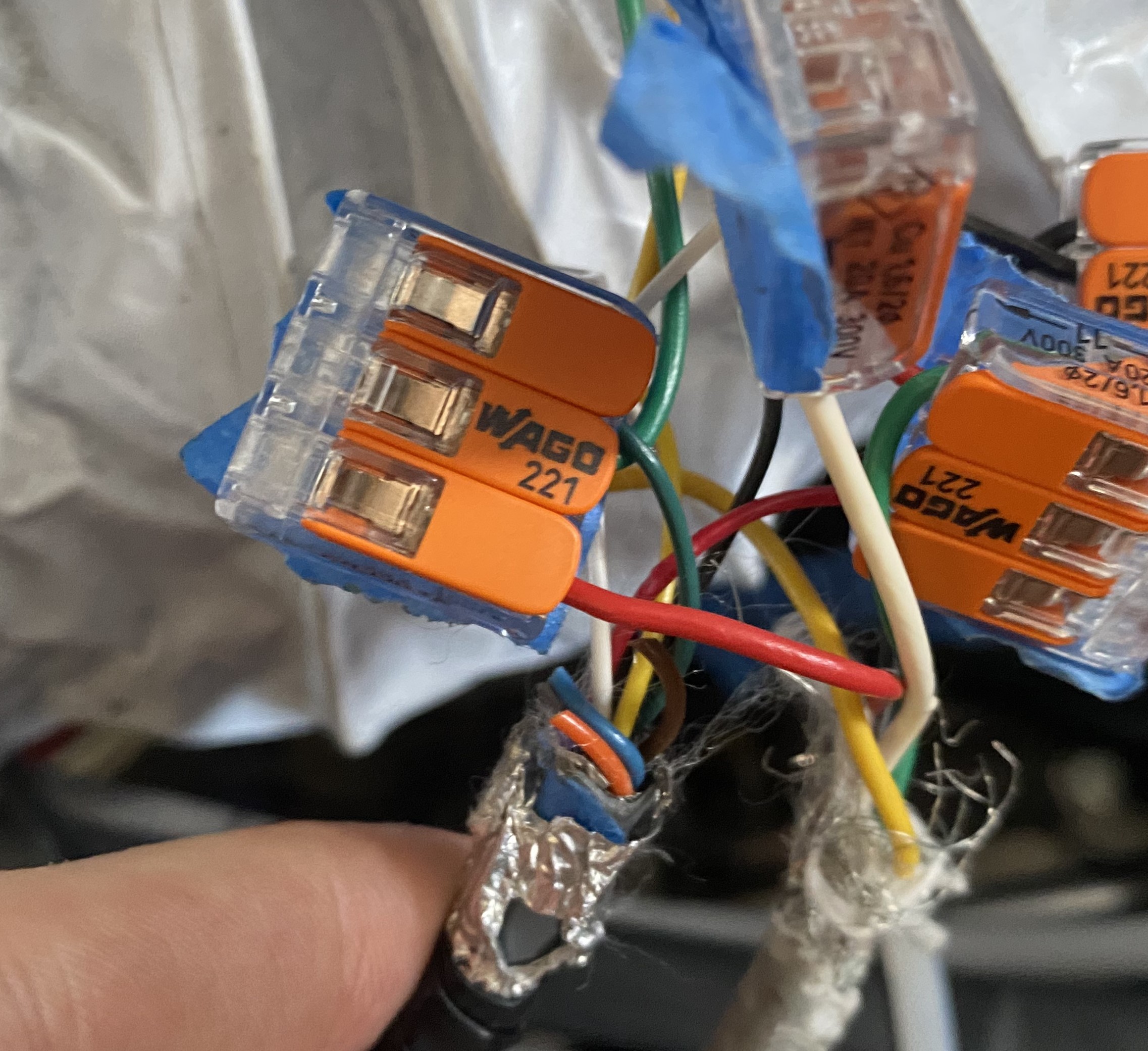
Notice that in this image the green wires are connected to the red wire. The primary issue was that the new motor’s wires were not coloured in the same order as our old motor. (Eg. instead of the red wire being phase A, it was phase B).
The motor oscillating back and forth suggested that the motor controller was frantically switching between two sets of coils that were right next to each other, pushing and pulling the motor back and forth.
The motor controller’s logic is hard coded into it, so it always does what it thinks is the proper switching to keep the motor spinning in a given direction (eg. forward or reverse). So, we were giving it improper data from the hall effect sensors and it was confused as to which state it was in.
To remedy this issue, we tried every possible set of connections between the motor hall effect sensor output wires and the motor controllers hall effect sensor input wires.
We labelled the motor controller’s terminals 1,2,3 and used the wire colors on the motor’s wires. Earlier we put some Wago connectors in series with the hall sense wires to be able to observe the voltages with an oscilloscope, so swapping the wires wasn’t an issue. We ended up driving our 5 official laps with these Wago connectors.
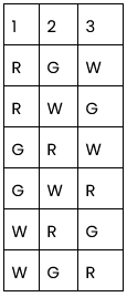
Every permutation we tried (index vs rows), last one was successful.
On the sixth attempt, we got smooth rotation from the motor (watch until the end!) and could drive the car. Great Success!