DRAFT DRAFT DRAFT Everything That Went Wrong For UBC Solar At FSGP 2025
Write another blog posts on insights from other teams
Write another one (maybe combine) about what to improve about UBC Solar, a vision for UBC Solar in 2028
What is required for WSC 2028
Maybe write one analyzing data from comp too on Influx
If you don’t do it, no one will.
IMAGE OF US AT COMP
Last summer, during the Formula Sun Grand Prix (FSGP) event in 2024 UBC Solar completed 94 laps (98 minus penalties). This year, we completed 5 official laps (during the first we got stuck at turn 18).
With a car that was already working from last year and a year to improve it, I (and presumably everyone else) expected to either match our previous results or surpass them. Instead, we did about 5% of the year before.
In this blog post I’ll describe all the technical issues we faced and broader organizational issues and what we missed in our preparation for competition.
We all pulled several all nighters and solved several seemingly impossible problems and learned a lot from comp. This was absolutely the most fun and rewarding experience of my life, but we did sevearly underperformance our results last year and this is worth examining.
In the next week I’ll write a couple more blog posts about comp. First, a summary of everything I learned from other teams, then using this info a vision for the future of UBC Solar, and then a review of FSGP competition data since 2021.
I took 5,211 words of notes during comp and all are available here.
Competition Preparation Last Year
The primary issues with UBC Solar’s preparation for FSGP 2025 is the lack of paranoia about keeping the car drivable and in a fully working state.
We raced last year and the car worked extremely well, enough to get 6th place out of 26 teams. This made us complacent about finding and fixing issues throughout the term and instead we made small changes that didn’t really improve probability of success during comp.
I’m on the Battery Management Systems (BMS) subteam and my project for 5 months was characterizing the main pack current sensor. In the end, this eliminated at most a 1.5 amp error for a 60 A max battery pack.
This is a nice feature and I learned a huge amount about our BMS and firmware programming, but this does not directly increase probability of success during comp (aside from Battery Scrutineering going slightly easier because we don’t have to explain to scrutineers that our current sensor is inaccurate).
In contrast, last year UBC Solar went through a mad dash before comp to get the car ready. All major components of the car were assembled just a couple months before competition and we had no spare time to nice-to-haves like an accurate current sensor. This meant the entire focus was getting the car to be successful at competiton, and this year instead the focus was on nice-to-haves until we noticed far too late that the car was not ready (mostly BMS issues, as you’ll see later).
My understanding is that our old Electrical lead, Mischa Johal, was particularly instrumental in getting the car ready for comp and he along with the rest of the team worked extremely hard. His blog post Reflecting On UBC Solar goes into detail about comp in 2024 and is an extremely useful read for anyone on an Solar Car team.
All the members were extremely familiar with the systems in the car prior to FSGP 2024 because they were the ones who built them and scrambled at the end to get it all integrated. This was a great team that put together a car that performed better than UBC Solar ever had. However, only two of the people who went to comp in 2024 went in 2025, Alex Malkowski (Mechanical lead), and Julie Ibrahimova (Previously Battery Mechanical lead and now captain).
This means the team as a whole was less prepared for comp than we were last year, especially since we didn’t get the valuable learning experience of frantically getting all the systems working prior to comp like we had in 2024.
What 2025 Competition Preparation Should Have Been
On the last day of competition an observer (observers make sure you don’t cheat by charging from the wall or do something too stupid) from ETS (A cracked solar car team), Antoine Lapointe, was observing our team as we debugged the motor before our final laps around the track. I had the opportunity to ask him 38 minutes worth of techical questions.
One of the most important insights was that ETS did 700 kilometers of testing on a track around Montreal before going to the World Solar Challenge this year. In contrast, UBC Solar had under 10 testing days and likely drove under 50 km total. Furthermore, all of our testing was focused on dynamics and not sustained driving. You can imagine that 94 laps around a track is more about sustained driving than dynamics (eg. faster turning and quick breaking).
AARJAV, JOSHUA!!!!! WHAT DISTANCE DID WE DRIVE IN PRE COMP TESTING????
ATTACH AUM VIDEO OF STRESS TESTING The most extreme testing was one of our drivers, Aum, stress testing the cars suspension / wheel wells by (seemingly extremely dangerously) driving in a circle around a parking lot.
If we had dedicated track days with the car where we aimed to drive 100 km for example, we would have been far more ready for comp.
Furthermore, the issues from comp last year should have been better communicated so that we could know what to expect. Not nice-to-haves, but what went horribly wrong. I don’t know exactly what happened last year at comp, but hopefully our next members (recruiting starts in 2 months!) will read this and get a good idea of what to expect and what to watch out for.
Both of these things could have been laid out as goals by our leadership. Fundamentally, a big choice like a 100 km track day can only be made by leadership. If one of the captain, mech lead, or elec lead decided we’d have a track day a month prior to comp we would have been far better prepared for competition (You guys are great, but we should have done better at comp and this is how we do better next time!).
This shows the high leverage impact that great leadership can have. One good decision early on, like decided we’d spend the money to have a track day and attempt 100 km, would have had a huge positive impact for competition.
Issue 1: BMS Voltage / Temperature Readings
Overview
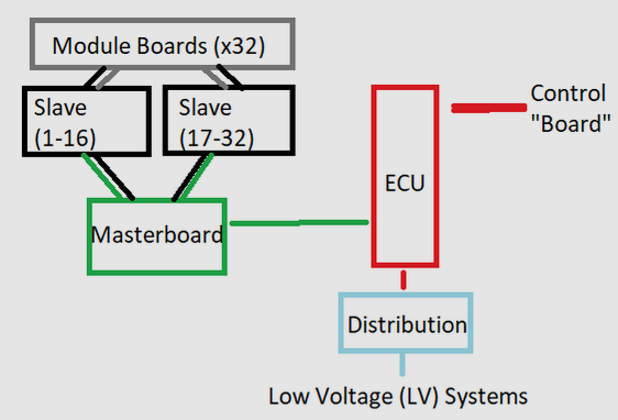
Our BMS architecture.
This is a slightly technically complex section in my area of expertise, so notes (see asterisks) are included for those who don’t work on Battery Management Systems. I won’t describe everything in extreme technical detail and instead focus on conclusions.
Overview:
- We make our own house Battery Management System (BMS)
- We use a masterboard-slaveboard-cellboard architecture.
- Cellboards have a voltage tap on each module and a thermistor.
- Slaveboards read from cellboards using an LTC6813 microcontroller and send data over isoSPI to the masterboard.
- The Masterboard aggregates all data and does computations like trigger a fault if we are at too high a temperature.
Debugging During Comp
The team arrived to the track on June 30th, the day before srutineering* began. After we got unpacked and I yelled “WE’RE AT COMP!!!” a critical number of times, we began testing the battery. As usual when working with our in-house BMS, this began an all-nighter of solving issues.
* Scrutineering is the process of real engineers scrutinizing your design by asking you technical questions and observer you perform a set of testing on your car and battery pack. Eg. break testing and observing stop time or simulating an over temperature while charging and seeing if your pack actually faults as expected.
INSERT GRAFANA IMAGE OF MODULE VOLTAGES? MISCHA BLOG HAS IT FROM ASC!
The first issue we saw is that some module voltage readings* were lower or higher than expected. On modules 21 and 22 we saw anomolous voltage reads that did not match the rest of the modules which were ~4.1 V. Depending on how the wire from the cell board (which holds the thermistor) to the slave board (which has the microcontroller reading voltage and temperature) was bent or if we touched it, we got a different voltage reading. Sometimes a module showed 1V, sometimes it was fine, sometimes it was >~4.1 V.
* Each module is a parallel line of cells. We have a 32s13p cell configuration with 13 cells in parallel per module and 32 total modules. Temperature and voltage sensing is done through a thermistor and an analog-to-digital (ADC) convertor on the LTC6813 chip we use.
Some more technical details about our battery are available here.
We also noticed that one modules was ~0.12 V lower than the rest of the modules. As you can see in our open source firmware, whenever there is greater than a 50mV difference between module voltage, we enable balancing resistors which dissipate excess energy from the modules that have too high voltage. This is the practice of passive pack balancing.
Krish Datta’s (BMS Colead) theory for why this happened is that somehow the MOSFET that toggles the balancing resistor was enabled during transport to competition and that one module was dissipating energy at some points during transport. After doing some quick math, it seemed that it would have been balancing for 5 total hours.
After replugging in all of the cellboard-to-slaveboard wire harnesses, replugging the isoSPI wire from the BMS masterboard to slaveboard and poking around the pack we came to the conclusion that we had several distinct issues.
- Touching the isoSPI wire harness between the masterboard and slaveboard 1 resulted in different data
- Touching the slaveboards at certain points resulted in different data
- Touching the slaveboard-cellboard wire harness sometimes resulted in different data
Our process for solving this issue involved replacing one of our slaveboards with a replacement we brought up before competition. Replacing it again with a mostly complete (missing LTC6813 micro controller) slave board again. Replacing one of the MOSFETs that toggle the balancing resistor. And swapping out the slaveboard-cellboard wire harnesses and masterboard-slaveboard isoSPI wire a few times.
We did all of this debugging during an all-nighter (I got soft and slept 90 minutes) in a frantic attempt to get the pack working for scrutineering the morning after so I likely got a few details wrong. Please correct me if I’m wrong anywhere here.
We Saw These Issues For Months Before Comp
Several months before competition the team began to shift focus from making small improvements to the car to getting it into a drivable state. As this campaign began and continued, we had endless issues with our in-house BMS, many of which remanifested themselves during competition.
IMAGE OF WIRES
IMAGE OF STRATEGY MAKING FUN OF CRIMPING WIRES
The quality of the crimps on the slaveboard-cellboard wire harness has been an issue for months and something we encountered again during competition. This is an unsolved problem and has delayed the car working for a non-trivial amount of time during competition. For the next generation we’ll likely swap the connectors we’re using from these small shitty Molex 8 pos connectors to some nicer big Molex Minifit ones.
Frying LTC6813 chips through either putting the module voltage tap jumpers on in the wrong order or ESD or other forms of operator error has set us back several weeks at minimum. If any future BMS member are reading this, think long and hard about your slaveboard design and failure modes, edge cases, and opportunities for operator error. You’re likely working on the most inscrutible board in the entire car, or even the entire UBC engineering design team building. Ensure you build your board good enough that members in 3 years won’t have months of issues.
In the end, we did finally get the BMS into a state where it worked well enough for the purposes of scrutineering and driving the car. I’m not sure anyone on the team fully understands the issues we faced from first principles and knows how to fully solve this for future generations of our car. The conclusion here is that every future BMS member has to be horribly paranoid about the edge cases in which their firmware or hardware doesn’t work.
Issue 2: Failing Wet Brake Testing A Few Times & Breaking The Accelerator Potentiometer
Details in this section mainly come from Alex Malkovski, our Mechanical Lead. Notes available here.
OBV INSERT IMAGE OR VIDEO
Wet Brake Testing involves accelerating your car to ~30 mph, then breaking to a stop while on wet ground. The first day we attempted this we failed due to taking too long to brake, or the car going out of control (hydroplaning such that the cars angle to the velocity vector was ~30 degrees).
In short, the issues were that a new untested breakplate pinched a breakline and caused interferance with a wire going to the accelerator’s potentiometer which ended up shearing the wire.
In the final couple of weeks before driving to competition, the mechanical team scrambled to instead a new base plate which the brake and accelerator pedals are mounted to. This base plate was installed on the Sunday before competition, we began driving on Wednesday morning.
Alex (Mech lead) was prepared to not install this new base plate before comp because of issues manufacturing it and how short notice it was.
The part was designed such that it required a CNC machine for machining on both sides and different fillet radii so multiple tool changes were required.
Our previous mechanical lead, Liam Andrew, is (was? graduated?) a student in the Integrated Engineering (IGEN) faculty of UBC. He was the only one on the team with access to a CNC machine in the IGEN shop.
This means manufacturing was complicated and delayed, since Liam Andrew is no longer an active member on the team. He had to come back last minute to finish up this project.
After the new baseplate was installed we only had one driving day on Monday before we left for comp. It was only at comp that we noticed that one of the breaklines was pinched between the master cylinder mount and a tab that holds the base plate. This was only noticed after a couple hours of dynamics testing at competition when the vehicle dynamics team was inspecting the car.
I believe the solution was rerouting the breakline.
POT IMAGE
The second issue due to the new base plate was interferance between a spring on the brake pedal (i think) and the wire that comes from the accelerator potentiometer.
This potentiometer is how we know how far the accelerator pedal is pressed, and hence is criticial comp hardware. So it was a critical issue when the wire to this potentiometer was severed.
The potentiometer we use is an apparently extremely rare female 10 kiloohm D-shaped shaft potentiometer that is no longer manufactured. We only have two of these, and our replacement was broken before comp and no one paid particular attention to the fact that this piece of comp-critical replacement hardware was broken.
I asked literally every team at comp and none of them had this exact component. Most teams used either off the shelf pedals, male potentiometers, or hall effect sensors for their accelerator pedals.
WIRE SHEARED IMAGE
Since the wire was sheared at it’s base, and the potentiometer is sealed with silicon (i think that’s the material), resoldering the wires on was a massive pain (Saman Niksiar, current electrical lead, suffered against this for a while!). One end of the variable resistor in the pot was shorted, so instead of a variable voltage divider, we had a variable resistor. We soldered on another resistor to the end to replicate the voltage divider functionality of a potentiometer.
For the next generation of the car, we should use more standard hardware that will at least stay in production a year after manufacturing the car! Hall effect sensors FTW!
Issue 3: MDI Inconsistent Power / CAN
GET AARJAVs HELP IN THIS SECTION. DID WE REFLASH MC AROUND HERE??
MDI PICTURE
On UBC Solar’s 3rd generation car, Brightside (Initials BS), we use a Mitsuba M2096 D3 motor and M2096 C2 motor controller. To control the motor controller, we have an interface board we called the MDI (wtf is the D in there? Motor Drive Interface? Rename this!).
During the third (maybe second, it all fades together with low sleep) day of scrutineering we attempted Wet Break Testing several times. Multiple times the behaviour we saw is that the car would begin to drive, but after a few seconds we would get a motor fault (i think, Aarjav pls confirm).
For about 12-24 hours this was an inscrutible issue and we had little idea how to fix it. Aarjav made some changes in this time right? Ask him about it and finish writing it later
PICTURE OF CAR GOING TO WET BREAK TESTING, IT WAS SCENIC
Eventually, while the car was on the way for Wet Break Testing at the end of day 3, the team found that when we press on the MDI CAN wire we see a change in the heartbeat of the MDI board. Either the heartbeat reset to 0 meaning it power cycles, or we didn’t get CAN messages from it.
Power and CAN to the MDI goes through a single connector, so this was clearly the issue.
IMAGE OF BULKHEAD
We also found that a wire going from the battery external power distribution board to the Driver Display board (DRD) was getting caught between a bulkhead and the aeroshell, putting extra tension on it and the connector, leading to an inconsitent connection.
DRD WIRE WAS REASON TEL WAS RESTARTING EDIT PLS AND DOUBLE CHEKC
We solved the DRD connection issue by rerouting the wire and the MDI wire issue by putting the wire in the connector again and making sure it was secure. This was an internal screw terminal connector, so we made sure the wires wouldn’t fall out of the screw terminal.
DOUBLE CHECK WITH MICHELLE THAT REROUTING IS ALL WE DID, MAYBE TAPE TOO, I DONT THINK WE RECRIMPED IT
The moral of the story is that you must always think about the tension that is being put on cables and how they will feel after 1000 kilometers and a years worth of driving.
This is an issue that only shows itself with time, which is also why even if you have a working car, you need to be paranoid about keeping it working.
- MDI connector and inconsistent power / CAN
a. Car intermittently wouldn’t move for an inexplicable reason
b. top shell hitting connector to DRD too
c. MDI connector bad
d. Tons of attempted motor reflashes to fix it? Fix what?
GETTING ON THE TRACK!!!!!
The Triumph of Getting on the Track
See the notes I took directly after the first lap here. Also mentioned in my messages to Alex Ezzat (former BMS lead, Mech lead, Elec lead, Team Captain)
After triumph at Wet Break Testing and sealing the pack with fishing line (A requirement that makes it harder for teams to cheat and access the pack), we could finally start driving on the track!
This was on day 4 of FSGP, the first track day. FSGP has 3 days of scrutineering and 3 track days. A few scrutineering events are not allowed to be attempted past day 4, including Wet Break Testing. Day 4 is when we completed Wet Break Testing. One day late and we would have done zero laps.
IMAGE OF THAT ONE TEAM WITH THE PETITION TO DO SCRUTINEERING
One team went around on the night of day 5 (4th of July!) asking for white board marker signatures on a petition to let them finish Scrutineering on the last day of FSGP. Sadly the Scrutineers didn’t let them!
VIDEO OF CAR ON THE TRACK
We were all extremely excited for the car to finally get on the track. We grinded for months and spent several all nighters during the last few days for this moment! My god how elated we all were! Just watch the video wow how amazing it was to see that!!!
Our Race Strategy team also wanted to get good data on their models of the car that day. So, the goal was to drive relatively fast at ~50 kmph to drain the batter to ~70% State of Charge (SoC). We all wanted to go fast and get laps on the board!
MAP OF TRACK AND TURN 18
A few minutes after seeing the car go out on the track the excitment began to subside. I walked back from the side of the track to the hot pit and saw Alex holding a radio. We heard Aum Wagh (Structures lead and driver) over the radio saying the car stopped moving right before turn 18.
IMAGE OF PIT AND TRACK
Some of our team was still by the track frantically waiting for Aum to come driving past the start line again. A few of us were back in the hot pit listening to the radio, knowing Aum wasn’t going to be doing another lap anytime soon, although we hadn’t lost all hope yet as all we heard is that the car wasn’t moving. Maybe this was solvable on the track.
VIDEO OF CAR CRAWLING
A few times Aum waited a couple minutes and restarted the car, then we could move again but just barely at a crawl, maybe not even a meter per second.
We were stuck on the track for what felt like about 30 minutes. Eventually, a Scrutineer told us we must get a safety car (van) from HQ to tow the car back to the garage. A few of us had already head out to HQ to do this a minute or two earlier.
IMAGE OF ALL MY BLUE ORIGIN SWAG I went back to the Blue Origin booth of the last day and asked for all the merch they would give me. This is how I slept that night in the trailer after my tent flooded due to rain the day before.
Side note: This scrutineer also worked at Blue Origin and Gail - primary organizer behind FSGP and ASC - told me he’s the reason Blue Origin sponsors the event. He also entertained about an hour of my questions at the Blue Origin booth.
IMAGE OF CANOPY AND ROLL CAGE
One downside with the desing is the fact that because the canopy opens forward and we tow from the roll cage, the canopy had to be removed for the car to be towed off the track. Someone had put Nylock nuts so an entire wrench set was required to take the canopy off and tow the car. Not ideal!
HOW CLOSE THE CAR GOT
As this was happening I was watching from the hot pit. The car got close enough that it was in view and we attempted to run towards it before a few Scrutineers / Attendants by the track informed us we could no go further than them onto the track.
We were painfully close to completing a lap - even if it was at <1m/s at the end - but as will become clear, this was not really in the set of possible outcomes.
There is a positive to this that since we didn’t technically complete a lap on day 2, we could still charge the pack from the wall overnight and didn’t need an observer watching us at all times looking for cheating. Charging from anything but the sun and regen is only disallowed once you complete an official lap. Getting towed or manually pushed off the track is obviously not an official lap.
Issue 4: Burning The Motor :(
As the car was driving onto the track for the first time, Saman and Alex both heard some sort of regular banging/ticking from the back of the car.
This was the most exciting part of our entire year so far and the culmination of years of work by over a hundred people. The car had been driving without much issue during dynamics testing that day (including Wet Break Testing) and we only had an hour left of track time. It was assumed that this noise was the standard noise the motor makes.
At low velocity, the motor doesn’t move evenly so it produces a clanking sound. This comes from the fact that the motor coils are attempting to move the motor rotor into the next local minimum of magnetic force. The electromagnets get just enough force to push the motor over into the next pair, and it falls into the next local minimum, making a clanking noise on the way down.
UPDATE THIS DESCRIPTION WITH HELP OF CHATGPT
IMAGE OF WHITE PLASTIC WIRE WRAP AROUND MOTOR POWER WIRES
However, this time the noise was something that had never been seen before. Opening the wheel well, Alex and Mueez Mughal (Vehicle Dynamics member) saw some of the white wrap around the motor power wires had come loose and saw hitting a socket head that mounts the break disc to the motor. On it’s own, there isn’t too much energy associated with this and this problem is solved by cutting that wire wrap a little shorter.
If we had checked out this issue we could have found something far more serious. The motor power wires that go to the electromagnets were rubbing against the rotating element of the motor.
At high velocity, this wire would rub against the inside coil until it reached high enough temperature to melt the plastic wire insulation and deposit it onto the motor windings.
A few minutes into the race Aum began smelling plastic burning from the back of the car. Throughout the entire race so far he heard the soft regular ticking noise of the plastic wrap hitting the break disc socket, until the noise of driving drowned it out.
IMAGE OF CAR OFF THE TRACK
Directly after the car came off the track Saman tried to touch the motor to get a feel for how hot it was. Well he did feel it was extremely how and pulled away his hand in pain immediately.
About 20 minutes later it was back in our bay. I put my hand on the bulkhead behind the tire and felt it was still hot enough that I wouldn’t want to keep my hand there for more than a minute.
AARJAV DEBUGGING TELEMETRY
During the race we didn’t get telemetry from the car so we didn’t know what was going on except from Aum over the radio (We have separate voice and telemetry radios).
Aarjav Jain (Embedded Systems lead) was debugging telemtry directly before the race, but didn’t have enough time to figure it out before the car went out on the track and didn’t think it was important enough to eat into our one hour of drive time left that day.
Aarjav later got data off the sd card in our CAN Bus Memorator and saw that the motor controller FET temperature got to 1XX C.
AARJAV WHAT WAS THE MAX MOTOR FET TEMP???
After the attempted lap, Aarjav told me to note for future reference that we should always have a spare of every communications device including radio modules, P-CANs (debugging device), and another person fully onboarded to our communications stack.
Future Members! For our next comp, don’t take this advice lightly.
ANOTHER IMAGE AS A SECTION BREAK
As Alex, Mueez, and Michael Hui-Fumagalli (Structures team member) got to the car they saw it was close enough to the track exit that it could be pushed there instead towing it.
They attempted to push the car by the roll cage and it just barely moved. Alex described this feeling as if the black calipers were locked onto the break disc.
Aum turned off the car and the car became far easier to push. Clearly the motor being energized was preventing the back right wheel from spinning (Remember, only one wheel is driven).
During this time Alex could smell something like burnt rubber from the power cables around the motor.
Everyone in the bay came over with our car jacks and we lifted the car onto them. This was an extremely scenic moment with the sun started to get low on the horizon, nice vibe even if we failed the first lap.
We rolled the car back to the bay while it was up on our custom jacks. Then, while the car was off, we tried spinning the motor and it seemed more poorly aligned than before, but it was mostly fine. However, when we attempted to spin the motor while the car was on, it would not budge a bit.
THOSE ARENT JACKS THEY ARE LIKE THE WOOD WHEEL THINGS WHATS THE RIGHT WORD FOR THEM???
We took the motor off to diagnose the issue and we saw a lot of black plastic deposited onto the motor. Our conclusion was that the heat shorted some of the phases inside the motor so that adjacent phases were powered simultaneously and keeping the rotor in place.
Again, Leadership is High Leverage And Important
This experience again goes to show the high leverage of leadership rolls. If any lead heard the new sound eminating from the end of the car and decided to use their authority to get everyone to stop and check out the issue before getting on the track, we could have saved the motor.
This isn’t unique just to team leads. Any member can point out an issue, but they have to go through the layer of (extremely quickly) convincing a lead that we should stop right before triumph to check out the issue.
We didn’t stop to check out the issue. So - like STS-51L - we suffered from Go Fever and went straight into the first lap, which doomed our motor to death.
Issue 5: Debugging New Motor
We tried removing the rubber with IPA. I slept that night and helped debug in the morning.
- Get new motor from the University of Toronto
a. Break caliper issue comes later
b. Attempt to use motor stand from illini? Berkeley?
c. Motor initially doesn’t work with our controller
d. It goes back and forth really quickly
e. Try a lot of things with Sasha (great guy)
f. it wasn’t deterministic interferance
g. Give motor LCR specs
h. Swap hall effect sense lines around to match motor power phase lines, then it works
i. The motor thinks it’s in reverse, 10A max, get to track.
j. Solve reverse issue after a few hours. (Aarjav pls expand here)
k. Now full power on the track! Max 75 kmph!
Issue 6: Brake Calipers Getting Stuck
- Break calipre issue
a. New motor from UofT has a thinner break disc
b. Show video
c. Break pad(?) falls out and stays there, stuck
d. Not constantly breaking on one edge of the break pad(?) and heating up
e. Motor FET temperature was also abnormally high