What Is the RCC_CSR Register in STM32 Microcontrollers?
Background
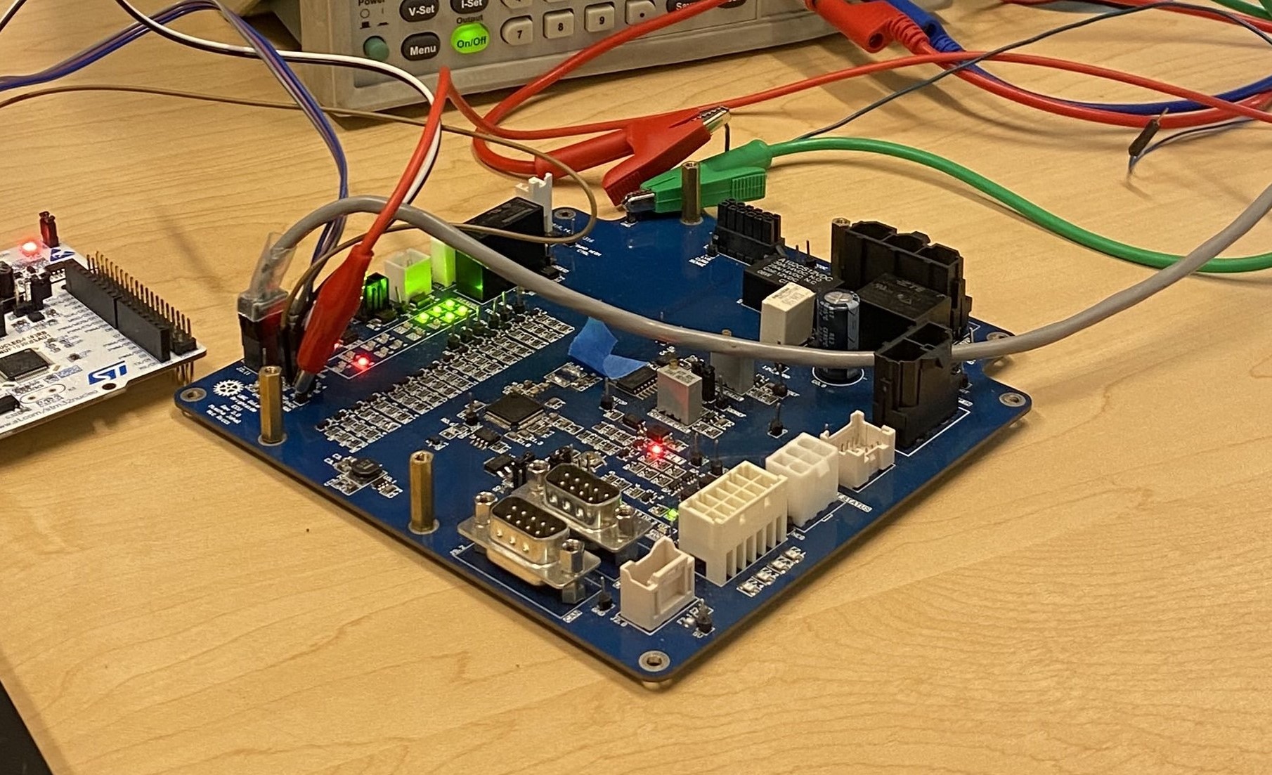
This is the board that controls UBC Solar’s Battery, the Elithion Control Unit (ECU). Absolute Beauty.
As mentioned in a previous blog post, I am a member of the UBC Solar Student Design Team where we build a solar powered car. UBC Solar remains a completely remarkable collection of technically capable individuals and an amazing team to be a part of.
During test a couple weeks ago, I shorted 3V3 and GND on the board that controls the battery, the Elithion Control Unit (ECU). (If you have suggestions for better acronyms that literally “ECU” pls dm me).
As described in this project update, this was completely my stupid mistake. To fix the issue, I came in almost every day after classes to work on the ECU. With help of a few other UBC Solar members (Michelle and Krish!), we soldered on a new microcontroller.
However, after soldering on the new MCU we saw that after flashing master code (that previously worked!) we would always be thrown into a fault state. After much debugging and trying to understand the system from first principles, we found that the issue was with the RCC_CSR_IWDG flag being high after every power cycle.
This blog post will explain the RCC_CSR register in STM32 chips, how we found out it was an issue with the ECU, and how we fixed it.
This blog post is mostly copied from a project update I wrote for UBC Solar, with some edits to make it slightly more understandable to non-UBC Solar members.
What is RCC_CSR Anyway?
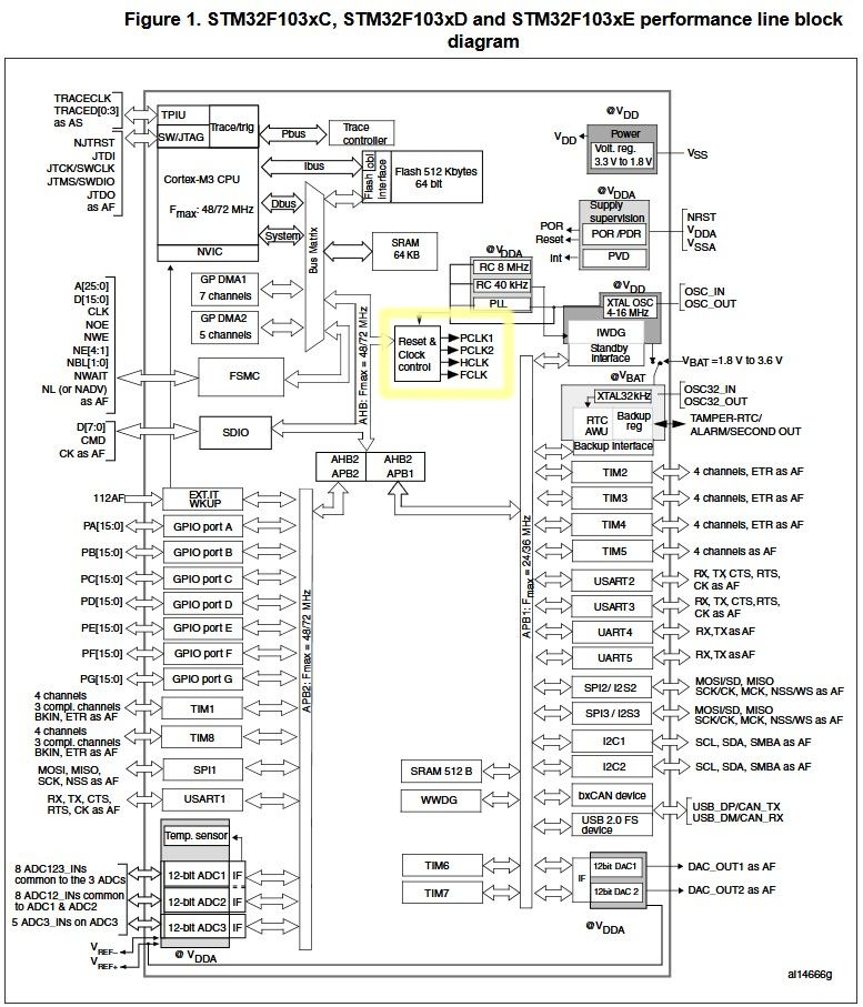
Highlighted here is the RCC section of the STM32 F103 microcontroller block diagram.
Every time an STM32 chip shuts down, it saves a bit that describes the reason it last shut down. These bits are in the Reset and Clock Control peripheral under the Control/Status Register. In code, this is RCC_CSR. This register is stored volatile memory, meaning its value should be reset every time the chip is powered off.
The pertinent bits for our purposes in the RCC_CSR register are:
LPWRRSTF (Bit 31): Low-Power Management Reset Flag.
WWDGRSTF (Bit 30): Window Watchdog Reset Flag.
IWDGRSTF (Bit 29): Independent Watchdog Reset Flag.
SFTRSTF (Bit 28): Software Reset Flag.
PORRSTF (Bit 27): Power-On Reset Flag.
PINRSTF (Bit 26): External Pin Reset Flag.
RMVF (Bit 24): Clear All Reset Flags.
These bits cover all reasons the STM32 could have shut down on the previous power cycle and when we power back up we can read this to know what happened.
RCC_CSR is a 32 bit register and the rest of the bits not mentioned about mostly have to do with clock control. It is called the Reset and Clock Control register, so the first 8 bits have to do with system resets, the rest have to do with clock control which we don’t care about here.
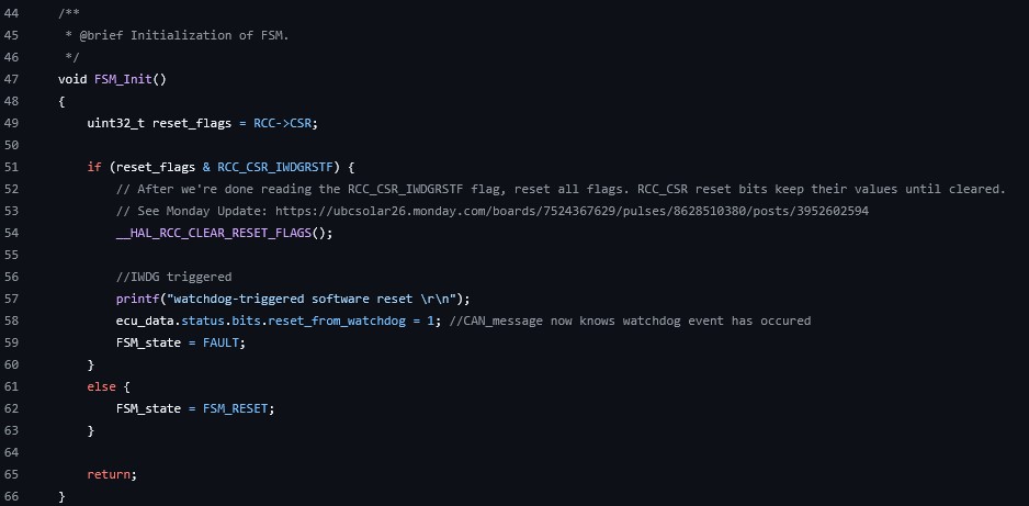
This shows initialization of the ECU state machine with the added line to reset the RCC_CSR flags.
During initialization of the battery state machine on the ECU we check the IWDGRSTF bit to see if the last shutdown was due to the independent watchdog. If it was, we go straight into a fault.
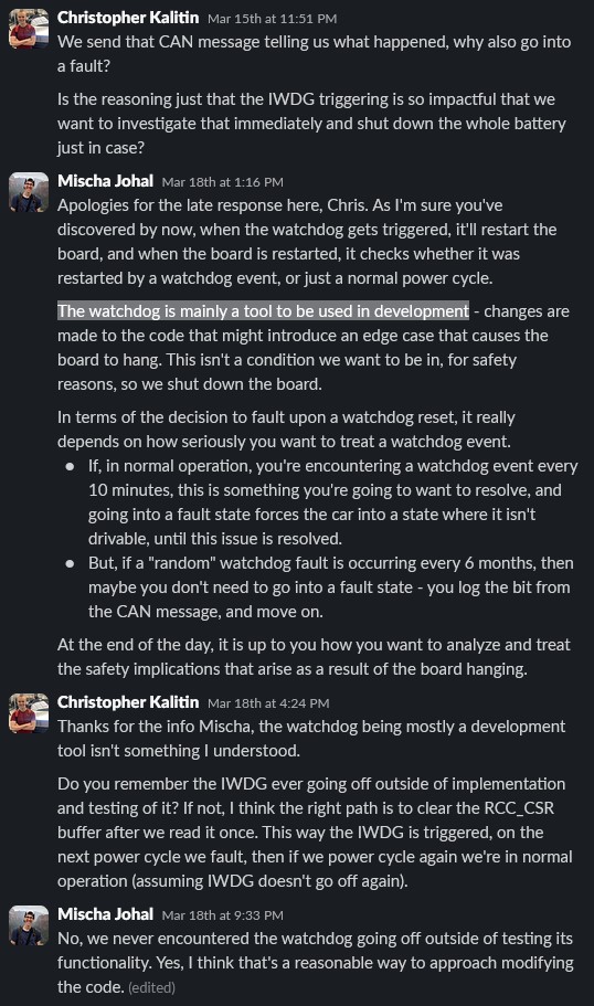
Mischa Johal (Previous UBC Solar electrical lead and wizard) explained to me that this is mainly a debugging tool. The independent watchdog on the ECU is triggered if there is ever a delay of >150ms between iterations of the main loop. This is a way to ensure the ECU is always running and not stuck in a loop.
Note:
RCC_CSR_IWDGRSTF is a C macro that represents bit 29 in the 32 bit RCC_CSR register. It’s just an easier way to access that value rather than doing some bit operations to get the value of the 29th bit in a 32 bit value.
There are two ways to clear the RCC_CSR register. First, if we set bit 24 high (RMVF, meaning Remove Reset Flag), the chip should clear the register values for us. Second, a Power-On Reset of the chip should clear the flags. A Power-On Reset occurs when voltage is cut off from the board, ie. wires are unplugged. Note that any other type of reset does not clear the register (eg. software reset, watchdog reset, reset button, etc.)
We set the RMVF bit high by calling this function:
__HAL_RCC_CLEAR_RESET_FLAGS();
The RMVF bit is the only bit that is writable out of all the reset-related bits in the register. For example, we can’t write the IWDGRSTF bit high to make it look like we reset due to the IWDG.
Testing The Reset Flags
Description of Testing
To ensure the RCC_CSR values were acting as expected, I tested some of them on the ECU.
In the main while loop, I added this code:
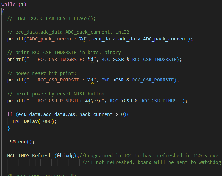
Look, for quick debugging ugly code is fine.
This prints the pack current and a few relevant bits in RCC_CSR.
I wanted a way to trigger the IWDG while the ECU was in normal operation. This way we could see a “natural” trigger of the IWDG.
In our ECU code, the IWDG is triggered whenever there is greater than a 150 ms delay between iterations of the main loop. This is counted as the time between calling the HAL_IWDG_Refresh function, which we do in every iteration of the main while loop.
Triggering the IWDG
I did a HAL_delay of 1000ms every time the ADC_pack_current was greater than zero. This delay triggered the IWDG.
Our HASS-100S main pack current sensor works by comparing the voltage of a reference value to the voltage output of the current sensor. The reference voltage is a constant 1.80V and the voltage output of the current sensor is proportional to the current. With this system, a 1.80V voltage output from the sensor corresponds with a current reading of 0A.
Since the current sensor wasn’t connected, the voltage output was 0V. This corresponds to a current reading of -233A.
With a jumper cable hooked up to a test pin on the current sensor line (Batt_curr_sense), I connected it to 3V3 so that the voltage reading from the current sensor would be 3.3V, which corresponds to a current reading of ~233A. Whenever the current reading was greater than 0 amps, I paused the code for 1000ms, which triggered the IWDG to power cycle the STM32 chip.
Results From Trying To Triggering Various RCC_CSR Bits
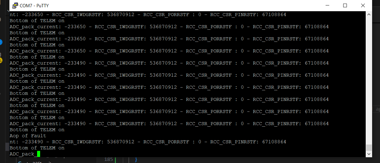
Print statements from testing is RCC_CSR is cleared after a power cycle. The non-zero values of RCC_CSR_IWDGRSTF and RCC_CSR_PINRSTF mean that the register was not cleared.
With my testing setup working, I first wanted to trigger the IWDG and see if it kept its value between power cycles. The expected behaviour is that power cycling the ECU (unplugging with the USB port, 3V3, or GND) would reset the IWDG bit.
I triggered the IWDG by setting Batt_Curr_Sense to 3.3V, then proceeded to power cycle the ECU in every way possible, but unplugging the USB port, then GND, then 3.3V. Every time I power cycled the ECU, the RCC_CSR_IWDGRSTF bit was unchanged.
This means the RCC_CSR_IWDGRSTF was never reset back to zero (which it should have mean). If this bit is ever high, we go straight into a fault. So, without a way to set this bit false, we were in a fault for eternity with no way to escape.
So, the only way to set that bit false is to call __HAL_RCC_CLEAR_RESET_FLAGS();
This is also the reason why we got issues with the ECU when we installed the new microcontroller. For whatever reason, the RCC_CSR_IWDGRSTF bit must have been high, so we were forever entering a fault at every start up with no way to stop it.
This issue must have never presented itself before because the IWDG never was triggered (or that bit was actually reset by a power cycle). This could have been extremely awkward at competition if the IWDG was set off and put the ECU into an unrecoverable state. It took us days to figure out this problem, days of debugging means no being able to drive during comp.
The solution is simple enough. We just need to clear the bits in RCC_CSR_IWDGRSTF after every startup. We only care about the reason we shut down last if it was due to the IWDG. In that case we go into a fault. So, after we run FSM_Init and check if the IWDG was triggered, we can clear the register by running the function __HAL_RCC_CLEAR_RESET_FLAGS().
That’s the most important conclusion from this testing, here are some other RCC_CSR testing observations:
- As mentioned before, the bit that represents a reset due to a power cycle (PORRSTF) was never triggered.
- The bit that represents a reset due to clicking the reset button (PINRSTF) was high every time I flashed code or after clicking the reset button. You can see this in the image above.
Aside on STM32 Flashing Debugging
Finally, I’d like to mention how I solved a recurring issue with being able to flash new STM32 projects to boards.
We’ve had the issue many times that after flashing a new STM32 project once, we weren’t able to flash code ever again, getting an error in both STM32 CubeIDE and PlatformIO saying something along the lines of “Target device not found.”
We would flash once, the code would work, then we couldn’t flash again.
If you ever have this issue, first check if you enabled Serial Wire Debug Mode:
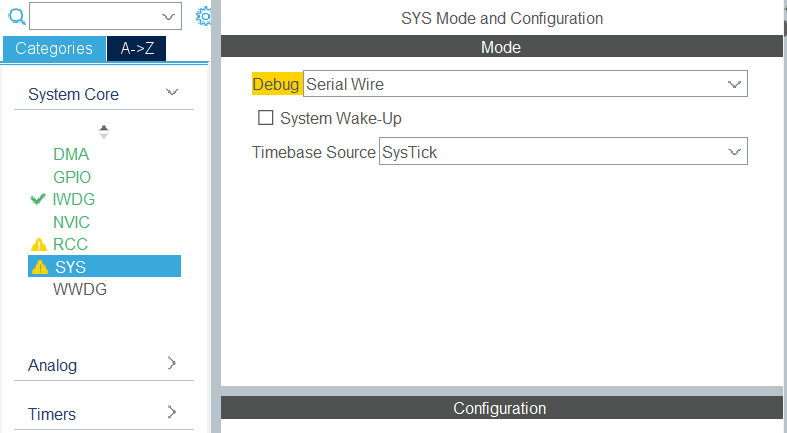
Setting Serial Wire Debug mode should allow you to flash code once again. However, for me this didn’t solve the issue.
Instead, what I had to do was short boot0 to 3V3. Power cycle the board. Then return the boot0 pin to GND. Then, reflash. This process resets some configuration in the STM32 microcontroller that ends up allowing us to flash again.
To future Chris or anyone else reading this, remember that! Short boot0 to 3V3 and power cycle!!!